
Shock Load and Impact Tolerance in Legged Robot QDD Actuators: A Procurement and Engineering Guide
Evaluate QDD actuator shock load tolerance with inertia examples, gear and bearing checks, and an RFQ checklist. Define impact tests before selecting a supplier.
QDD actuator shock load tolerance cannot be inferred from peak motor torque alone. For legged robot procurement, compare the expected joint torque waveform, radial and axial forces, tilting moment, impact count, and driver state against documented component limits and a representative assembly test. A low gear ratio can reduce reflected motor inertia, but gear strength, bearing support, available joint travel, and regenerative energy handling still determine whether a particular module survives.
This guide helps purchasing and hardware teams turn those questions into an RFQ and sample acceptance plan. Start with the worked inertia comparison, then use the manufacturing evidence table, failure-mode matrix, and supplier checklist to identify missing evidence before approving a joint.
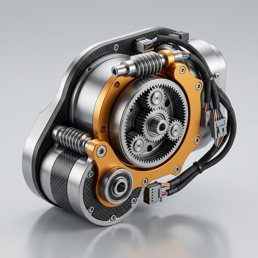
Reviewed: October 27, 2026. Scope: Global OEM programs selecting QDD joints for humanoids, quadrupeds, and related dynamic mechanisms. Limitations: This is a desk-based engineering guide, not a QDD Motors impact-test report, product rating, or safety certification. Numerical examples are illustrative calculations. Actual limits require the selected geometry, material, controller, mounting, and duty cycle. The cover image and diagram are illustrations, not an inspection drawing or test evidence.
Preparing an actuator RFQ? Use our custom motor engineering review to discuss your load envelope and required validation records. Our OEM motor manufacturing support page outlines the broader sourcing workflow.
1. The Physics of Impact Attenuation: Reflected Inertia and Backdrivability
When a robot foot contacts the ground, the output joint can experience a rapid torque change. The response depends on the complete leg mechanism: contact compliance, transmission friction, rotor inertia, controller behavior, and the joint's ability to move. A rigid stop or locked brake can remove the benefit of backdrivability.
The Reflected Inertia Bottleneck
For an ideal rigid transmission, the motor contribution to output-side inertia scales with the square of reduction ratio:
J_ref,motor = J_rotor × N²Here J_rotor is rotor inertia in kg·m² and N is motor speed divided by output speed. Gear and linkage inertia must be added after referring each moving element to the output axis. This calculation alone does not predict peak tooth stress or impact force.
Consider two illustrative motor-and-ratio combinations, excluding gearbox inertia, friction, compliance, and active control:
- 100:1 reduction:
0.00005 × 100² = 0.50 kg·m²reflected motor inertia. - 6:1 reduction:
0.00025 × 6² = 0.009 kg·m²reflected motor inertia.
The first motor contribution is approximately 55.6 times the second. These assumed inputs demonstrate the ratio-squared relationship; they do not establish equal torque, equal mass, or a measured shock-survival advantage between products. Ask suppliers for actual rotor inertia and backdrive torque over temperature and speed.
Mechanical Transparency and Energy Handling
A joint that can yield may redirect some impact energy into motion rather than concentrating it in local deformation. The MIT Cheetah actuator-design publication provides relevant research context for proprioceptive actuation and impact mitigation; it is not a rating for every QDD module.
Backdriving can also generate electrical energy, depending on speed, winding constants, and inverter state. Rotor motion stores kinetic energy; compliance stores elastic energy. Neither is automatically a dissipative sink. Winding losses or a brake resistor dissipate energy, while a receptive DC supply or battery may accept regeneration. A bus capacitor stores only a finite amount:
E_cap,available = 0.5 × C × (V_limit² − V_initial²)Use capacitance in farads and voltage in volts to obtain joules. This ideal estimate excludes component tolerances, ESR, wiring inductance, and protection behavior. Check the complete energy path and overvoltage response with the actual driver and battery state; backdrivability alone does not establish an attenuation percentage.
Diagram: conceptual energy paths, with no universal gear-ratio or force threshold. On narrow screens, scroll horizontally to read the labels. Joint travel, friction, braking state, and the electrical energy sink must be checked together.
2. Quantifying Gear Tooth Fatigue under Shock: ISO 6336
A peak current specification does not establish a gearbox's mechanical transient limit. Request the allowable output torque waveform, its duration, permitted repetitions, direction, speed, and temperature, plus the failure criterion used to set the rating.
ISO 6336-1:2019 describes principles and influence factors for spur and helical gear load-capacity calculations. The series supports gear design comparisons; it does not assure assembled drive-system performance. The public scope also excludes failure mechanisms such as plastic deformation and case crushing from its rating formulae. A fatigue calculation therefore cannot replace an overload assessment and assembly testing.
Select Application Factors from the Load Spectrum
The application factor K_A accounts for external loading in the chosen rating method. It is not a universal legged-robot constant. Ask the gear designer to document the method, standard edition, load history, load-sharing assumptions, and both bending and contact checks. Avoid counting the same shock twice if it is already included in the input load spectrum.
For an illustrative 50 Nm reference torque and 150 Nm event, the event/reference ratio is 3.0. That ratio does not automatically become K_A, establish a fatigue life, or prove a 150 Nm assembly rating. Retain the pulse shape, repetition count, and reversing loads in the assessment.
Tooth Contact under Carrier Deflection
Planet-pin and housing deflection can shift tooth contact toward an edge. Lead crowning, tip relief, root geometry, and carrier support can help, but their dimensions depend on tooth size, face width, alignment, and load. Request a loaded contact-pattern assessment and inspection report rather than prescribing one crown height or fillet radius for every actuator.
3. Metallurgical and Manufacturing Specifications for Shock Endurance
Use this table to compare supplier evidence against your specific drawing and load envelope. The entries are review questions, not a universal aerospace grade or a guarantee that one material or process will survive an impact.
| Component / Parameter | Evidence to Request | Engineering Decision | Acceptance Boundary |
|---|---|---|---|
| Gear Material Grade | Material certificate, process route, and lot traceability | Evaluate alloy, cleanliness, and toughness with the gear designer; carburizing grades such as 20CrMnTi, 18CrNiMo7-6, or AISI 8620 are candidates | A grade name alone does not establish strength or life |
| Heat Treatment | Qualified cycle, hardness profile, distortion and inspection records | Match surface wear resistance and core strength to the design | Set hardness limits on the approved drawing |
| Effective Case Depth | Measured depth profile, test method, and sampling location | Check the case against tooth size and subsurface stress | Do not copy a fixed depth across different modules |
| Tooth Surface and Geometry | Profile, lead, pitch, roughness, and contact-pattern reports | Assess load distribution with the actual carrier deflection | Specify inspection limits and measurement conditions |
| Planet Carrier and Pins | Drawings, fits, stiffness analysis, and reversing-load evidence | Compare pin support and load sharing across planets | Validate assumptions at the assembled mounting stiffness |
| Rotor Magnet Retention | Adhesive process, retention design, and thermal/shock qualification | Assess magnet retention over the operating envelope | A sleeve or wrap requires its own clearance and loss assessment |
| Output Bearing System | Exact bearing model, preload, load ratings, and mounting instructions | Compare radial, axial, and moment demand simultaneously | Bearing type alone is not an impact rating |
How to Evaluate Powder Metal Gearing
Powder metallurgy spans different densities, alloys, and processing routes. Do not infer impact survival from the process label alone or impose an unsupported blanket ban. Require material and density records, heat-treatment evidence, applicable design allowables, and representative tooth and assembly tests. If the supplier cannot substantiate the required load envelope, keep the part unapproved for that duty.
4. Bearing Architecture and Moment Rigidity under Lateral Impacts
An off-axis ground force creates a moment about the bearing support. For a simple perpendicular force and lever arm, M = F × d. An illustrative 1,200 N force acting 0.08 m from the support gives 96 Nm. This is a moment calculation, not a predicted landing force; actual sizing also requires force direction, joint pose, dynamics, and the installed load path.
Cross-Roller Bearings vs. Ball-Bearing Arrangements
Cross-roller rings can support combined loads in a compact envelope. A spaced ball-bearing or angular-contact arrangement may also meet the requirement. Compare the actual bearing size, span, preload, fits, lubrication, housing stiffness, and friction rather than assuming a fixed stiffness advantage for one architecture.
The THK cross-roller ring static-safety guide relates basic static load rating to equivalent applied load. Its table gives a minimum static safety-factor guideline of 5 for vibration or impact, and recommends 7 or more when considering dynamic performance such as service life. These are that product family's selection guidelines, not a universal robot-joint acceptance criterion.
Use the selected manufacturer's combined-load calculation and installation limits. A static safety factor does not establish fatigue life, impact-cycle endurance, or immunity to raceway indentation. Request post-impact checks for stiction, backlash, runout, and bearing condition alongside the load calculation.
5. Structural Failure Modes in Dynamic Actuation: Diagnosis and Countermeasures
This matrix is an engineering screening aid, not a report of QDD Motors field failures. Agree test severity and pass/fail limits from the application before comparing supplier results.
| Failure Mode | Possible Root Cause | Affected Subcomponent | Design Review Question | Verification Evidence |
|---|---|---|---|---|
| Tooth Root Fracture | Single overload or accumulated bending fatigue | Sun and planet gears | Are tooth geometry, material, and load sharing adequate for the waveform? | Stress review plus representative overload and endurance tests |
| Tooth End Chipping | Misalignment or edge contact under deflection | Gear flanks | Do carrier stiffness and flank modifications maintain acceptable contact? | Loaded contact-pattern inspection and post-test teardown |
| Planet Pin Movement | Reversing loads, fit loss, or retention weakness | Carrier and pins | Are fit and retention adequate over temperature and reversing loads? | Reversal test with pre/post dimensional and backlash measurements |
| Raceway Indentation | Excessive combined force and moment | Output bearings | Were equivalent load, preload, and housing stiffness assessed together? | Load calculation, post-impact running torque, and raceway inspection |
| Magnet Movement | Retention degradation under thermal and mechanical loading | Rotor | Is the retention method qualified for this rotor and environment? | Relevant thermal/shock test and rotor inspection |
| Encoder Error | Readhead displacement, connection fault, or scale damage | Position sensing | Are mounting and readhead limits compatible with measured displacement? | Logged position/error behavior during and after the defined test |
| DC Bus Overvoltage | Regenerated energy exceeds the available sink | Driver and power bus | Does the sink work at the worst battery state and driver mode? | Backdrive test recording bus voltage, current, protection events, and recovery |
6. Supplier Vetting and RFQ Procurement Checklist
A useful RFQ defines the load and the evidence needed for approval. An unspecified “shock resistant” claim should remain an open item.
- Joint load envelope: Supply joint location, robot configuration, torque-time traces, radial/axial forces, moments, speed, and uncertainty. Identify measured inputs separately from simulation assumptions.
- Event definition: Define pulse shape, duration, direction, repetition count, joint position, and interval between impacts; distinguish normal gait events from exceptional stumbles or falls.
- Material traceability: Request gear and carrier certificates, processing route, lot identification, and the approved drawing revision.
- Heat-treatment evidence: Agree hardness, case-depth method where applicable, inspection locations, and sampling; obtain measured records rather than nominal process labels.
- Geometry and carrier evidence: Request tooth inspection, loaded contact assessment, pin-fit details, and analysis assumptions tied to the required torque spectrum.
- Bearing evidence: Identify the exact model, preload, mounting fits, combined-load calculation, and the manufacturer's applicable static and life criteria.
- Assembly test configuration: Record mounting stiffness, attached inertia, joint travel, temperature, driver mode, brake state, bus voltage, and regenerative sink. Obtain calibrated sensor traces and adequate acquisition bandwidth for the pulse duration.
- Acceptance and repeatability: Agree sample count and numerical limits for pre/post backlash, stiction, runout, encoder errors, and electrical faults. Specify teardown criteria, rejection rules, and how sample testing relates to the required service life.
- Energy and retention checks: Include worst-case bus energy handling and magnet retention conditions. Check power-off or protection states where relevant to the intended duty.
- Change control: Tie approval to a BOM, firmware, process, and drawing revision; require notification and requalification when a critical parameter changes.
Evidence handoff: Send this checklist, your load traces, and the unresolved items to the custom motor engineering team for a requirements review. A supplier's willingness to test is useful, but approval should depend on the agreed results.
7. Application Boundaries: When QDD Is Useful vs. Alternative Architectures
Where QDD Can Be a Strong Candidate
- Humanoid and quadruped leg joints: Low reflected inertia and backdrivability can support dynamic interaction, subject to available travel, torque-speed demand, and validated assembly limits.
- Wearable mechanisms: Low impedance may be useful, but wearer safety also requires independent assessment of faults, joint limits, stopping behavior, and the complete device.
- Mobile mechanisms exposed to repeated impacts: Evaluate the actual force path; wheel or linkage shocks may load bearings differently from the motor's nominal torque duty.
When to Consider Other Mechanical Strategies
- Series elastic elements or compliant feet: Consider these when controlled elastic travel and energy storage suit the mechanism. Check deflection limits, resonance, fatigue, and control response.
- Torque-limiting clutches: Consider a calibrated limiter where overload release is acceptable. Check release tolerance, wear, re-engagement, and the consequence of lost torque transmission.
- Higher-ratio transmissions: These may suit demanding holding or positioning requirements. Compare efficiency, backlash, reflected inertia, and impact ratings using actual products; neither a low ratio nor a high ratio establishes overall suitability.
8. Total Cost of Ownership (TCO) and Lifecycle Economics
Compare quotes with the same duty, validation scope, and warranty conditions. There is no universal QDD price premium or documented failure-rate reduction established by this guide.
TCO = purchase + integration + qualification
    + expected failures × (replacement + repair labor + downtime)
For an illustrative calculation in a common currency, suppose a candidate costs 80 more per joint and each avoided field failure would save 400. Ignoring other differences, the premium breaks even at 80 / 400 = 0.20 avoided failures per installed joint over the chosen service period. These assumed costs are not supplier quotes or observed failure rates. Use your own validation results, service records, and sensitivity ranges before claiming savings.
Current-based torque estimation can be useful in a QDD system, but friction, acceleration, temperature, and calibration affect accuracy. Do not remove force sensors from a procurement budget unless the system's sensing and safety requirements have been validated with the proposed architecture.
9. Frequently Asked Questions (FAQ)
What is the difference between peak intermittent torque and dynamic shock load capacity?
Peak motor torque is usually bounded by current, temperature, speed, and a specified duration. Shock capacity concerns the mechanical assembly and the applied pulse, combined loads, and repetition count. Request both definitions and test conditions; neither rating can be substituted for the other.
Why can a low gear ratio help during a ground impact?
The motor contribution to output-side inertia scales as rotor inertia times reduction ratio squared. A lower ratio can make yielding easier, but friction, joint stops, attached inertia, control, and brake state can dominate the actual response. It does not guarantee a particular reduction in peak force.
Can impact regeneration damage the motor driver?
Yes, if energy returned during backdrive exceeds the capacity of the bus and its energy sink. Check voltage/current traces, battery charge acceptance, capacitance, braking hardware, and fault behavior. Back-EMF is a speed-related motor voltage; it is not, by itself, the same quantity as the rise in DC bus voltage.
How does tooth lead crowning help under dynamic loading?
Crowning can reduce edge contact when the gear support deflects or is misaligned. Its amount must suit the geometry and load range; excessive modification can reduce the effective contact area. Request loaded contact analysis and measured tooth geometry rather than a universal micrometer value.
Are cross-roller bearings always better for legged joints?
No. Compare combined-load capacity, stiffness, installation, preload, friction, and life for the complete arrangement. A compact cross-roller ring can be useful, while another bearing arrangement may also satisfy the duty. Neither architecture prevents damage under an unspecified impact.
What gear steel grade should be specified in the actuator RFQ?
Ask the gear designer to propose a grade and heat treatment supported by calculations, traceability, inspection, and representative testing. Carburizing steels are possible candidates, but a material name alone does not determine case depth, core toughness, tooth geometry, or allowable impact loading.
10. Conclusion and Next Steps
Select a QDD actuator by its documented load envelope and evidence, not by a peak-torque multiplier or an architecture label. Low reflected inertia is useful only when the installed mechanism can yield and the mechanical and electrical paths can handle the event.
Before sample approval, close three questions: What event must the joint survive? What calculations support the design? What representative assembly test and acceptance limits demonstrate the required behavior? Keep unresolved loads or missing evidence visible in the RFQ rather than treating them as a pass.
For your next review, share joint geometry, load-time histories, expected impact count, operating conditions, and available power-bus information with our OEM motor manufacturing support team. Our custom motor engineering workflow can help structure the requirements and evidence handoff.
Sources & References
Sources checked October 27, 2026. These references support the design framework and stated selection boundaries; they do not establish a QDD Motors product rating or field-test result.
- ISO 6336-1:2019: Calculation of load capacity of spur and helical gears — Part 1: Basic principles, introduction and general influence factors. Official ISO record and public scope. Use with the applicable calculation parts and a qualified gear designer; the public abstract is not the full normative method.
- P. M. Wensing, A. Wang, S. Seok, D. Otten, J. Lang, and S. Kim (2017): Proprioceptive Actuator Design in the MIT Cheetah: Impact Mitigation and High-Bandwidth Physical Interaction for Dynamic Legged Robots. IEEE Transactions on Robotics. MIT Biomimetic Robotics Lab publication record. Research context, not a general shock-capacity specification for commercial QDD joints.
- THK: Cross-Roller Ring — Selection Criteria: Static Safety Factor. Official combined-load and static-safety guidance. Apply the selected bearing family's current criteria and mounting conditions; static selection is distinct from assembly impact endurance.
Author

Categories
More Posts
Dual-Encoder Architecture in Robotic QDD Actuators: Joint-Side Deflection Compensation, Magnetic Shielding, and Functional Safety Procurement Guide
Specify dual-encoder QDD actuators: compare joint deflection, magnetic shielding and BiSS-C timing, then use an RFQ checklist to request supplier test evidence.
Selecting Frameless Torque Motors for Surgical Robotics: A Procurement and Engineering Guide
Specify frameless torque motors for surgical robotics with procurement checks for cogging torque, thermal limits, hollow bores, and QDD Motors support.
Electromagnetic Holding Brakes in Robotic QDD Actuators: Power-Off Gravity Protection, Release Coil Thermal Management, and Fail-Safe Joint Integration
Select electromagnetic holding brakes for QDD actuators. Compare power-off torque, coil heat, release timing, and supplier tests; prepare your integration RFQ.