
Dual-Encoder Architecture in Robotic QDD Actuators: Joint-Side Deflection Compensation, Magnetic Shielding, and Functional Safety Procurement Guide
Specify dual-encoder QDD actuators: compare joint deflection, magnetic shielding and BiSS-C timing, then use an RFQ checklist to request supplier test evidence.
Dual-encoder QDD actuators measure both motor rotation and joint output position, making transmission deflection observable under load. A motor-side encoder supplies rotor angle for Field-Oriented Control (FOC); a joint-side encoder measures the output after the gearbox. This combination can improve loaded positioning when gearbox compliance dominates the error budget. It does not remove mechanical backlash, guarantee torque-sensing accuracy, or establish functional safety certification.
For mechatronics engineering leads, control architects, and technical procurement teams, sourcing a dual-encoder Quasi-Direct Drive (QDD) actuator requires comparing sensor installation accuracy, hollow-shaft clearance, magnetic interference, synchronized sampling, and documented safety capabilities. Start with the torsional deflection model, audit communication timing, and agree on acceptance evidence before releasing production purchase orders.
Published and reviewed: November 6, 2026. Scope: Global OEM engineering and sourcing teams evaluating integrated QDD actuators and hollow-shaft robotic joints for humanoids, quadrupeds, and industrial manipulators. Limitations: This is a desk-based engineering and procurement guide, not a report of measured product performance. The worked example uses explicitly assumed inputs. Actual stiffness, magnetic immunity, timing, and safety performance require validation on the selected assembly. Medical use and human-contact operation require separate application qualification; no certification is asserted here.
Explore our QDD actuators, robot joint motor modules, and hollow-shaft joint motors. To prepare an RFQ with encoder protocols and bore dimensions, review our custom motor engineering and OEM assembly testing workflows.
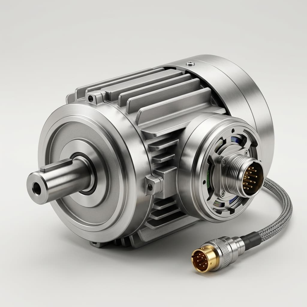
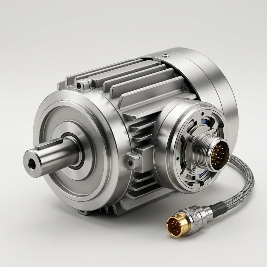
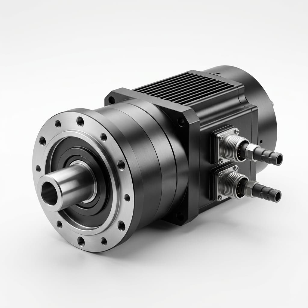
Figure 1: Illustrative motor image showing a finned housing, shaft, and connector. It does not establish an internal dual-encoder layout, through-bore dimension, or tested product performance; request assembly drawings and qualification records for the proposed part.
1. Why Motor-Side Feedback Can Miss Joint Deflection Under Load
A motor-side encoder measures the rotor relative to the motor housing. Dividing its angle by the reduction ratio estimates the joint angle only to the extent that the transmission behaves as a rigid, calibrated connection:
theta_joint_ideal = theta_motor / NHere N is the reduction ratio, with motor and joint angles expressed in the same units and referenced to aligned zero positions. A low reduction ratio reduces some transmission penalties but does not eliminate elastic deformation or lost motion.
The Physics of Transmission Compliance
Planetary gear teeth, carrier plates, shafts, and bearings all contribute compliance. Backlash and friction introduce direction-dependent behavior, while temperature changes clearances and sensor offsets. For a positive resisting load, a simplified quasi-static model is:
theta_joint = theta_motor / N - tau_load / K_theta + e_residualtau_loadis output-side resisting torque in N·m.K_thetais output-referenced torsional stiffness in N·m/rad when angles are in radians. Convert stiffness expressed in N·m/arcmin before using it.e_residualis a signed angular residual representing backlash history, calibration offsets, and thermal effects. It must be characterized rather than inferred from a material's linear expansion coefficient.
This model applies within a calibrated load range, away from strong dynamic resonances. Stiffness may depend on load, direction, and temperature. Under acceleration, motor and link inertia and damping also matter. A joint-side encoder measures the angle at its mounting location; deformation downstream of that location remains outside its measurement.
Worked Engineering Example: End-Effector Error Propagation
Consider an illustrative shoulder joint with these assumed values:
- Reduction ratio:
N = 8. - Torsional stiffness:
K_theta = 12,000 N·m/rad, equivalent to approximately3.49 N·m/arcmin. - Additional worst-case lost-motion allowance:
3.5 arcmin = 0.001018 rad. - Effective arm reach:
L = 0.85 m. - Resisting load torque:
tau_load = 48 N·m.
The 3.5 arcmin value is an assumed full error allowance in this calculation, not an automatically applicable half-backlash value. Confirm how the supplier defines backlash before adding it to an error budget.
Elastic deflection = 48 / 12,000 = 0.004000 rad
                  = 13.75 arcmin
Worst-case angle allowance = 0.004000 + 0.001018
                           = 0.005018 rad
                           = 17.25 arcmin
Transverse tool displacement = 0.85 * sin(0.005018)
                            = approximately 4.27 mm
The example shows how one joint can consume several millimeters of a positioning budget. It is not a measured QDD actuator result. The displacement assumes a transverse lever-arm geometry; a complete multi-joint robot requires a Jacobian-based error analysis. Other joints, link bending, bearing tilt, and thermal offsets must be budgeted separately. Joint-side feedback can help correct the measured deflection within available torque and stable control bandwidth, but cannot restore physical rigidity.
Why Output-Only Sensing Complicates FOC Commutation
FOC needs an estimate of the rotor's electrical angle, determined by mechanical rotor angle, pole-pair count, and calibration offset. A joint encoder after a compliant gearbox cannot uniquely recover instantaneous rotor angle through ideal ratio scaling. Motor-side sensing is therefore a useful direct input for commutation, especially at standstill and under changing load.
An output-only arrangement is not inherently unstable: observer-based and other control strategies exist. Its suitability depends on speed range, load dynamics, observability, and the drive implementation. Likewise, a single motor encoder can be adequate when loaded joint accuracy requirements are modest.
Selection rule: Add joint-side feedback when the load-side error budget or diagnostics justify it. Require the supplier to identify which feedback closes each loop and how the design handles gearbox resonance, rather than accepting sensor count as a performance specification.
2. Dual-Loop Control Kinematics & Virtual Torque Estimation
A common cascaded architecture uses output position feedback for the outer loop and motor feedback for commutation and the inner motion loop. This is an illustrative topology, not a mandatory implementation:
Position target
      |
      v
Joint position loop <--------- Joint encoder
      |
Velocity / torque request
      |
      v
Motor velocity controller <--- Motor encoder
      |
Current request
      |
      v
FOC current controller <------ Phase current sensors
      ^
      +--- Rotor angle from motor encoder
      |
Inverter -> Motor -> Gearbox -> Joint output
The motor encoder feeds the motor controls; the joint encoder closes the load-position loop. Specify actual current-loop, velocity-loop, and position-loop update rates separately. A controller executing at 20 kHz does not have a 20 kHz mechanical bandwidth. Filtering, sampling delay, gearbox resonance, and phase margin determine usable disturbance rejection.
Proprioceptive Virtual Torque Sensing
Two encoders can support torque estimation by treating the calibrated transmission as an elastic element. To use the same positive resisting-load convention as Section 1, define motor-referred output deflection as:
delta_theta(t) = theta_motor(t) / N - theta_joint(t)
tau_estimated = K_theta * delta_theta
              + D_theta * d(delta_theta)/dt
D_theta is an effective damping coefficient in N·m·s/rad. The two positions must be zero-aligned, unwrapped, and time-aligned. Subtract measured unloaded offsets before estimating torque. Otherwise, an encoder index error can appear as a persistent torque bias. Differentiation also amplifies noise, so the damping term requires filtering and validation.
A stiff gearbox produces only a small measurable twist. With the example stiffness, an output-referenced angle uncertainty of 0.01 degree alone corresponds to approximately 2.09 N·m of torque uncertainty. That calculation uses 12,000 * 0.01 * pi / 180; it excludes stiffness uncertainty, friction, hysteresis, and timing errors. More output bits do not automatically deliver better installed accuracy.
This estimate may support impedance control or development diagnostics after testing. It does not establish a universal percentage accuracy or replace a qualified torque sensor for a safety function. Compare both approaches using calibrated torque references, bidirectional loads, representative temperatures, and the required frequency range. Ask whether the reported error is full scale, percent of reading, or an absolute torque bound.
3. Physical Cross-Section & Magnetic Shielding Architecture
The conceptual stack below identifies interfaces to inspect in supplier drawings. It does not specify dimensions or certify an existing catalog assembly:
Joint output flange
  |-- Joint encoder target and fixed readhead
  |-- Output bearing and gearbox carrier
  |-- Evaluated magnetic isolation / flux return
  |-- Motor stator and rotor
  |-- Motor encoder target and fixed readhead
  `-- Inverter and synchronized acquisition

Through-bore and moving cable harness:
check clearance across the entire stack and joint travel.
The output target should follow the member whose position matters to the application. A readhead mounted on a flexible cover can add apparent motion unrelated to gearbox twist. Confirm target retention, bearing runout, axial float, concentricity, and access for calibration. For a hollow joint, request the minimum usable passage through connectors, seals, and bearing supports, rather than relying on the magnetic ring's nominal inner diameter.
A multipole magnetic track alone is periodic and does not necessarily provide a unique single-turn absolute angle. Ask how absolute coding, startup alignment, or additional tracks resolve pole ambiguity. A single-turn motor angle also cannot establish the absolute output angle after multiple motor revolutions through a gearbox unless turn state or a joint reference resolves the ambiguity.
4. Encoder Sensing Technologies Compared: Sourcing Trade-Offs
Magnetic, optical, inductive, and resolver-based feedback can all be appropriate. The table is a qualitative screening framework; technology names do not establish shock ratings, ingress protection, accuracy, or price.
| Sourcing parameter | Magnetic ring | Optical disc or ring | Inductive target | Resolver | Evidence to request |
|---|---|---|---|---|---|
| Absolute position | Requires suitable coding | Requires absolute track design | Depends on target and electronics | Usually single-turn angle | Startup behavior and ambiguity handling |
| Installed accuracy | Sensitive to target and mounting | Sensitive to scale and mounting | Sensitive to target geometry | Includes converter error | Full-revolution calibrated error map |
| Hollow-bore integration | Ring layouts can suit bores | Ring layouts also possible | Planar annular layouts possible | Hollow versions available | Complete clearance drawing |
| Shock and vibration | Assembly retention matters | Disc material and supports matter | PCB and target supports matter | Windings and bearings matter | Test level, pulse, axes, duration, and operating state |
| Contamination | Sensing can tolerate some contamination | Optical path needs protection | Often tolerant of nonconductive contamination | Housing and insulation matter | Complete assembly sealing and ingress report |
| Electrical interference | External magnetic fields matter | Electronics and cables still face EMC | Coupling and electronics need evaluation | Excitation and conversion need evaluation | Installed current-on angle-error data |
| Temperature | Magnet and IC limits matter | Light source and scale limits matter | PCB and electronics limits matter | Insulation and converter limits matter | Accuracy and drift across agreed temperatures |
| Packaging and cost | Include target and calibration | Include sealing and alignment | Include target and electronics | Include excitation and converter | Comparable installed BOM and service scope |
For an impact-loaded leg joint, shortlist assemblies with relevant retention and shock evidence. For a precision wrist, prioritize installed angular accuracy and repeatability across temperature and load. Encoder resolution describes digital increment size; accuracy describes error relative to a reference. Neither guarantees end-effector performance independently of the robot mechanics.
5. Stray Magnetic Flux & Shielding in High-Current Hollow-Shaft Motors
Stator end-turns, permanent magnets, phase conductors, and brakes can expose encoder electronics to interfering fields. The risk depends on geometry, current, field direction, sensor architecture, and switching spectrum. An optical sensing principle avoids magnetic angle detection, but its readout electronics and communication wiring still require EMC evaluation.
A Reproducible Screening Calculation
For a long isolated straight conductor in free space, a useful preliminary estimate is:
B = mu_0 * I / (2 * pi * r)
mu_0 = approximately 4 * pi * 10^-7 H/m
I = 80 A, r = 0.010 m -> B = approximately 1.6 mT
This is an illustrative field estimate, not an assembled motor simulation. Return conductors, phase cancellation, winding shape, steel saturation, and rotor magnets change the actual field. A measured external field also cannot be converted directly into angular error without the encoder's directional sensitivity and target-field characteristics.
Potential symptoms include current-correlated angle error, velocity ripple after differentiation, and diagnostic faults. Establish the cause with synchronized current and angle logs rather than assuming every positioning anomaly is magnetic interference.
Shielding Measures and Acceptance Evidence
Three measures deserve review:
- Sensor architecture: Differential sensing can reject common-mode fields, but gradients, saturation, mismatch, and mounting errors limit rejection. Request the IC's specified field-immunity conditions and installed results.
- Flux management: A high-permeability shield or modified flux-return path may help. Material, thickness, openings, forming stress, heat treatment, saturation, and frequency response determine effectiveness; there is no universal shield thickness or attenuation figure.
- Geometry and wiring: Separation from end-turns and careful routing of phase and signal pairs can reduce interference. Validate the actual layout instead of prescribing one minimum air gap for every motor.
Test the selected assembly against a reference encoder with current off and on, both current polarities, multiple rotor positions, representative PWM settings, and cold/hot conditions. Define safe stall duration and cooling before high-current testing. Record peak and RMS current conventions, reference uncertainty, angle drift, and diagnostic events.
IEC 61000-4-8 addresses power-frequency magnetic immunity; it does not by itself establish immunity to local motor fields or PWM harmonics. Agree on an application-specific current-on acceptance test alongside the applicable EMC requirements. Any numerical angular-error limit belongs in the buyer's error budget and contract, rather than being presented as a universal standard limit.
Need a supplier comparison? Send the expected duty cycle, bore envelope, and angular-error budget through custom motor engineering, and ask which test records are available for the proposed configuration.
6. Serial Protocols & Real-Time Determinism: BiSS-C vs. Competitors
The two encoders should provide identifiable, time-aligned samples to the local drive or controller. Evaluate sensing delay, sample skew, frame transfer time, communication jitter, and control computation separately.
The BiSS Association describes BiSS as an open interface supporting short cycles, CRC protection, and daisy-chaining. These capabilities make it a candidate for dual feedback; they do not establish one guaranteed actuator latency or cable length.
For an illustrative 20-bit position word, two status bits, and a 6-bit CRC, the 28 data bits alone take 2.8 microseconds at 10 MHz. A complete acquisition also includes protocol overhead, sensor processing, cable delay, and timeout. Two chained positions increase the frame length. Require measurements for the actual encoder profile and master hardware, including handling of invalid or stale data.
Protocol Integration Comparison
This table compares integration questions, not laboratory benchmarks. SSI variants, EnDat generations, and EtherCAT configurations must be evaluated by their exact implementation.
| Procurement question | BiSS-C | SSI | EnDat | EtherCAT joint module |
|---|---|---|---|---|
| Interface boundary | Encoder to master | Encoder to master | Encoder to compatible master | Network to integrated drive |
| Timing evidence | Complete frame and sensor delay | Frame, pause, and acquisition delay | Version-specific frame and processing | Network cycle plus local loop timing |
| Integrity evidence | Profile CRC and status handling | Verify implemented parity or checks | Verify version-specific checks | Network checks plus local sensor validation |
| Dual sensing | Confirm master and chain support | Confirm channels and acquisition skew | Confirm supported topology | Confirm both raw values are exposed |
| Wiring evidence | Full pinout, power, shield, and return | Full pinout and electrical levels | Encoder-specific pinout and power | Network, power, grounding, and local wiring |
| Safety evidence | Ordinary CRC is insufficient | Requires a qualified safety architecture | Verify safety option and manual | Verify safety option and full function |
| Selection criterion | Master compatibility and measured timing | Required rate and diagnostic behavior | Supported encoder/drive combination | Whole-module synchronization and diagnostics |
Ordinary BiSS-C CRC checks do not establish safe communication. The separate BiSS Safety profile specifies redundant position data, distinct CRC protection, and a life counter. Verify the actual sensor, receiving logic, and safety manual; a protocol name does not certify the actuator.
7. Functional Safety Procurement: ISO 13849-1 and IEC 61800-5-2
Human-contact and collaborative applications require a machine-level risk assessment and safety-function specification. ISO 13849-1:2023 provides a methodology for safety-related control-system design and integration; it does not assign the required performance level for every application. Applicable market rules and robot-specific requirements must be assessed for the intended deployment.
What Dual Encoders Contribute
Motor and joint measurements can support plausibility monitoring, but two physical sensors do not automatically provide independent safety channels. Shared power, clocks, firmware, targets, communication hardware, or mechanical references can introduce common-cause failures. Normal elastic twist, gear ratio, zero offsets, turn tracking, and sampling delay must be included in cross-check thresholds.
Motor angle / ratio ----+
                        | -> Validity and plausibility monitor
Joint angle ------------+       |
                                v
                      Validated safety logic
                                |
                                v
                      Defined safe reaction
This sketch is conceptual and carries no Category, PL, or SIL claim. Higher mean time to dangerous failure (MTTF_d) is preferable. Category, diagnostic coverage, common-cause measures, software, and validation collectively affect achieved performance; no single diagnostic-coverage percentage or sensor count establishes PL d/e.
Safety Functions to Specify and Verify
IEC 61800-5-2 addresses functional safety of electrical power drive systems. Procurement should identify the particular functions and their implementation boundaries:
- Safely-Limited Position (SLP): Define monitored position limits, reference validity, and the reaction when a limit is exceeded. Human presence detection needs its own validated input where required.
- Safely-Limited Speed (SLS): Define the monitored speed, threshold, measurement uncertainty, and response time from the application risk assessment. There is no universal collaborative TCP speed inferred from having two encoders.
- Safe Direction (SDI): Define prohibited direction, allowed motion tolerance, and reaction to a detected violation.
- Safe Stop 1 / 2 (SS1 / SS2): SS1 performs controlled stopping followed by STO; SS2 performs controlled stopping followed by Safe Operating Stop (SOS), with drive power maintained. Brake control is a separate design consideration.
STO prevents torque generation by the drive; it does not mechanically hold a gravity-loaded link or guarantee a short stopping distance. Brakes, load paths, stored energy, and stopping behavior need independent assessment. Encoder monitoring does not remove the need for guarding or other protective measures identified by the risk assessment.
Procurement rule: Request the safety manual, certificate scope where certification is claimed, dangerous failure rate (PFH_d), mission time, diagnostic assumptions, fault-reaction time, and permitted configurations. Confirm the exact encoder, drive, firmware, brake, and transmission combination. Require documented integration and validation evidence before accepting a claimed safety function.
8. Sourcing & RFQ Engineering Checklist: 10 Actionable Audit Items
Use the following checklist to distinguish a plausible architecture from a production-ready offer. Set acceptance thresholds from the application error budget and operating envelope.
- 1. Two real measurements: Obtain motor and joint position words, mounting references, zero definitions, and logs proving that the output value is measured rather than synthesized from motor angle.
- 2. Resolution and accuracy: Specify required installed accuracy, repeatability, and increment size separately. Ask for full-revolution error maps and reference uncertainty; do not substitute a bit count for positioning performance.
- 3. Thermal calibration: Define ambient, winding, and encoder temperatures and the allowable drift. Request cold-start and thermally stabilized records, including compensation method and stored calibration version.
- 4. Magnetic immunity: Agree on current-on tests at the intended continuous and peak conditions, with safe duration and cooling. Record error against a reference and any diagnostic trips.
- 5. Shielding rationale: Review flux paths, readhead placement, material condition, and wiring. Accept a design based on demonstrated immunity, including when another validated approach avoids a dedicated shield.
- 6. Timing and protocol: Identify the exact interface profile, clock, frame size, sample timestamp, inter-channel skew, worst-case delay, and invalid-frame response using the intended drive.
- 7. Mechanical tolerances: Obtain allowable runout, axial float, air gap, target retention, and bearing-load conditions from the selected sensor and joint drawings. Verify the installed tolerance stack.
- 8. Absolute state retention: Separate single-turn from multi-turn capability. Specify behavior after power loss, unpowered movement, battery depletion, and gear-ratio wraparound; require a demonstrated recovery sequence.
- 9. Safety documentation: For each required safety function, check claimed performance, certificate/manual scope, integration assumptions, and validation responsibility. Keep unqualified channels outside the claimed safety function.
- 10. Acceptance and traceability: Agree on sample qualification versus per-unit end-of-line tests. Request bidirectional torque-angle curves, hysteresis, calibration records, serial-number traceability, and explicit disposition of failed units.
For the stiffness test, define fixture compliance and output reference location before measuring. Sweep positive and negative torque at controlled speed, record temperature, and separate slope from reversal hysteresis. Repeat near the intended operating load rather than reporting only an unloaded calibration. A supplier should identify whether each report covers the proposed configuration, a related design, or the individual shipped actuator.
9. Frequently Asked Questions (FAQ)
What is the primary difference between dual-encoder QDD actuators and motor-encoder-only servos?
A motor-encoder-only servo measures rotor position before the transmission. A dual-encoder arrangement also measures the joint output, exposing load-side motion that the motor measurement can miss. Correction depends on controller stability, available torque, mounting location, and measurement accuracy. Neither architecture is universally required for every robot.
Can a dual-encoder setup eliminate the need for a dedicated joint torque sensor?
Sometimes, for a validated control or diagnostic task. Torque estimation from twist requires calibrated stiffness, aligned samples, and compensation for friction and hysteresis. The worked uncertainty calculation in Section 2 shows why small angle errors matter. Dedicated sensing may still be necessary for the required accuracy, bandwidth, or safety function.
Are magnetic encoders always preferable to optical encoders for humanoid limbs?
No. Compare complete assemblies under the intended shock, contamination, thermal, and magnetic conditions. IP ratings belong to qualified enclosures or assemblies, rather than to a sensing principle. Optical electronics still need EMC evaluation, and magnetic assemblies still need target retention and field-immunity evidence.
How does stator current interfere with magnetic encoders?
Motor conductors produce fields that can distort the target field at the readhead. The effect depends on direction, geometry, sensor rejection, and saturation. Evaluate angle error with current off and on across rotor positions. A specified shielding alloy alone does not establish immunity.
What serial protocol should procurement teams specify?
Choose the interface supported by the intended encoder and controller with demonstrated acquisition timing and diagnostics. BiSS-C is one candidate, including for compatible daisy-chained sensors. The full acquisition delay matters more than a headline clock rate; ordinary protocol integrity checks also need to be distinguished from safety-qualified communication.
How do dual encoders improve functional safety?
They can provide additional measurements for fault detection and plausibility checks. Shared failures, normal compliance, calibration, and timing must be handled by a validated safety design. Two encoders alone do not grant Category 3/4, PL d/e, or a particular fault-response time.
Does thermal expansion affect dual-encoder calibration?
Yes. Mechanical offsets, target geometry, magnet properties, and electronics can change with temperature. Request installed error data at cold start and thermal equilibrium and verify the supplier's compensation approach. A lookup table helps only within the conditions for which it has been validated.
What hollow bore diameter should our engineering team request?
Size the passage from the actual cable and hose bundle, bend radius, strain relief, connectors, rotational travel, and service access. Check the narrowest point through the entire joint. Joint location alone does not determine a valid bore diameter, and the encoder ring opening may exceed the usable cable passage.
10. Sources & Reference Standards
Sources checked for this review on November 6, 2026. These references establish their stated scope and interface features; they do not verify any QDD Motors product rating or the assumed worked-example inputs.
- ISO 13849-1:2023 — General principles for design: Official ISO record for safety-related control-system design and integration. The application must establish its required safety functions and performance levels.
- BiSS Association — Interface overview: Official overview of open-interface features, CRC protection, short cycles, and daisy-chaining. Encoder and master specifications determine actual timing.
- BiSS Association — BiSS Safety: Official explanation of redundant position words, distinct CRCs, and life-counter checks. Profile capability does not certify an integrated actuator.
- IEC 61800-5-2:2016 — Safety requirements, functional: Standard designation for drive safety functions discussed in Section 7. Obtain the applicable licensed edition and supplier safety manual for procurement; this guide does not reproduce the normative requirements.
Sourcing & Custom Engineering Support
Specifying dual-encoder QDD actuators requires balancing mechanical rigidity, installed sensing accuracy, hollow bore clearance, thermal behavior, and control timing. Use the model and checklist above to compare offers under the same load case and acceptance criteria.
Explore the QDD actuators catalog, robot joint modules, and hollow-shaft joint motors. Send your mechanical envelope, torque-speed duty cycle, error budget, controller interface, and required safety functions to our custom motor engineering team. Ask which drawings, calibration records, and test reports can be supplied for the exact proposed configuration through OEM manufacturing support, then agree on any additional qualification before production release.
Author

Categories
More Posts
48V vs. 96V QDD Motors for Humanoid Robots: A System-Level Procurement Guide
Compare 48V vs 96V QDD Motors for humanoid robots with thermal, cable, safety, supply-chain, and RFQ checks for global OEM teams.
Continuous Torque Derating and Thermal Impedance in Robotic QDD Actuators: A Procurement and Engineering Guide
Compare QDD continuous torque derating, thermal impedance and RMS duty cycles. Use the engineering example and RFQ checklist to request supplier test evidence.
Electromagnetic Holding Brakes in Robotic QDD Actuators: Power-Off Gravity Protection, Release Coil Thermal Management, and Fail-Safe Joint Integration
Select electromagnetic holding brakes for QDD actuators. Compare power-off torque, coil heat, release timing, and supplier tests; prepare your integration RFQ.