
Electromagnetic Holding Brakes in Robotic QDD Actuators: Power-Off Gravity Protection, Release Coil Thermal Management, and Fail-Safe Joint Integration
Select electromagnetic holding brakes for QDD actuators. Compare power-off torque, coil heat, release timing, and supplier tests; prepare your integration RFQ.
Electromagnetic holding brakes in robotic QDD actuators must satisfy three separate requirements: retain a gravity load after power loss, release reliably when hot, and tolerate any dynamic stops assigned to them. A static holding-torque rating alone cannot establish all three. Low reduction ratios increase the torque needed at a motor-side brake compared with a high-ratio joint carrying the same output load. An energized release coil also consumes part of the sealed actuator's thermal budget.
For hardware engineering leads, powertrain designers, and technical procurement teams, this guide connects brake sizing, pulse-and-hold coil control, drive sequencing, and supplier acceptance evidence. Start with the worst-case load and permitted motion after a fault, then select the brake and its control architecture.
Published and reviewed: November 2, 2026. Scope: Global OEM engineering and sourcing teams evaluating QDD actuators and hollow-shaft robotic joints. Limitations: Numerical examples are hypothetical, reproducible calculations, not QDD Motors test results or product ratings. Brake availability, minimum hot holding torque, release current, response time, stopping work, and safety functions require model-specific evidence. This supplier-authored guide does not establish functional safety certification or a universal brake requirement for any robot class.
Explore our integrated QDD actuators, modular robot joint packages, and hollow-shaft joint motors. Send your load case and envelope to our custom motor engineering team to discuss brake integration feasibility.
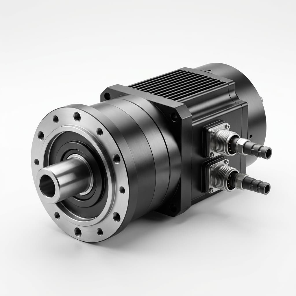
Cover image: a hollow-shaft actuator illustration; it does not establish that the pictured assembly contains a brake.
1. The Physics Contradiction: Backdrivability vs. Gravitational Collapse
Low reduction ratios reduce motor inertia reflected to the output: J_reflected = J_rotor × N², where N = motor speed / joint speed. The MIT Cheetah actuator paper provides research context for low-ratio actuation and impact interaction; it is not a brake qualification study.
A backdrivable joint can move under gravity when motor torque disappears. Do not count gearbox drag as a holding device without a validated minimum holding capability across temperature, wear, lubrication, and load direction. A high reduction ratio alone does not establish self-locking either.
Mathematical Sizing Formulation
For preliminary static screening, take no credit for gearbox friction:
T_brake,ideal = T_gravity,max / N
T_brake,static,min,hot ≥ S_margin × T_gravity,max / N
T_gravity,max includes the payload and all supported link masses at the worst pose. T_brake,static,min,hot is the supplier's guaranteed minimum holding torque under the agreed hot, worn, and installation conditions. The margin must follow the project's risk and uncertainty assessment; it is not a universal certification factor.
During backdriving motion, a simplified power balance gives T_motor,backdrive ≈ η_reverse × T_joint / N. Reverse efficiency multiplies the reflected torque in that moving-load model; dividing by it is not the correct transformation. At zero speed, use validated static behavior rather than treating a running efficiency as a static brake rating.
Worked example, not a product recommendation: A 50 N·m gravity load with an illustrative margin of 1.5 gives the following frictionless screen. The same assumptions apply to both columns.
| Sizing Parameter | 100:1 Joint Example | 8:1 QDD Joint Example | Procurement Implication |
|---|---|---|---|
| Maximum output gravity torque | 50 N·m | 50 N·m | Record worst pose and payload |
| Reduction ratio N | 100 | 8 | Confirm brake location and load path |
| Ideal motor-side load torque | 0.50 N·m | 6.25 N·m | Divide output load by ratio |
| Illustrative design margin | 1.5 | 1.5 | Replace with project-approved margin |
| Minimum hot brake torque for this screen | 0.75 N·m | 9.375 N·m | Compare guaranteed minimum, not nominal cold torque |
| Relative brake torque demand | 1× | 12.5× | Ratio comparison holds only for the same load and margin |
| Gearbox friction credit | None | None | Do not infer safe retention from efficiency |
| Diameter, mass, and release power | Supplier-specific | Supplier-specific | Request CAD and coil data; torque alone cannot predict them |
A motor-side brake also depends on the reducer, couplings, and output connection remaining intact. If the required protection must survive a transmission failure, evaluate an independent output restraint or another validated load-support mechanism.
2. The "Release Coil Thermal Trap": Parasitic Heat in Sealed Actuators
A spring-applied, electrically released brake uses spring force to clamp a friction disc without coil power. Energizing its coil attracts the armature to release the disc. Other brake architectures can have different power-loss states; verify the selected model instead of assuming every electromagnetic brake is power-off holding.
For constant DC voltage:
P_coil = V_dc² / R_coil(T)
R_coil(T) ≈ R_coil(20°C) × [1 + 0.00393 × (T - 20°C)]
At 100°C, this copper-resistance approximation gives about 1.314 times the 20°C resistance. At the same applied voltage, current and electrical power decrease as resistance rises; the concern is reduced magnetic release margin, not an electrical resistance runaway. A current-regulated driver instead needs additional voltage headroom and can dissipate more winding heat as resistance rises.
Brake heat, motor copper and iron loss, and drive loss share the housing's heat-removal paths. The amount that reaches the stator or encoder depends on mounting and thermal coupling. Do not infer a fixed torque derating percentage, encoder drift, or housing temperature rise from coil watts alone.
For the RFQ, request a coupled thermal test at the intended ambient, mounting interface, motor duty, and brake-release duty. Use IEC 60034-1:2026 as a motor rating and performance reference where applicable; its catalog scope does not qualify the complete actuator or brake system.
3. Dual-Stage Overexcitation Control (Pulse-and-Hold / PWM)
A spring-applied brake may need more current to pull its armature across the open gap than to keep it released after the gap closes. A supplier-approved pulse-and-hold driver can exploit this difference. Reduced-power operation is conditional on the coil and driver specification; some models require continuous nominal excitation.
The Two-Stage Drive Implementation
- Pull-in stage: Apply the manufacturer's permitted voltage or regulated current for its permitted duration. Validate release at the hottest coil, minimum supply, maximum cable drop, and worst air gap. Overvoltage is allowed only when the manufacturer specifies it.
- Released-state hold: Reduce current only after release is established. Validate the minimum released-state current with supply tolerance, temperature, vibration, and aging. Coil current alone does not prove the armature moved.
- De-energization: Specify the recirculation and discharge-clamp circuit. A slow freewheel path can delay engagement; a higher clamp voltage must remain within coil, switch, insulation, and EMC limits.
Quantitative Thermal Savings
The following example assumes a fixed hot resistance of 38.4 Ω and low-ripple current. It compares electrical operating points only; it does not establish that 7.5 V will keep any particular brake open.
P_24V = 24² / 38.4 = 15.00 W
I_7.5V = 7.5 / 38.4 = 0.1953 A
P_7.5V = 7.5² / 38.4 = 1.4648 W
Reduction = 1 - (7.5 / 24)² = 90.23%| Operating Metric | Nominal-Voltage Example | Reduced-Current Example | Validation Boundary |
|---|---|---|---|
| Assumed hot coil resistance | 38.4 Ω | 38.4 Ω | Held equal to isolate the arithmetic |
| DC or average low-ripple voltage | 24 V | 7.5 V | Reduced point requires supplier approval |
| Approximate steady current | 0.6250 A | 0.1953 A | Measure current and ripple |
| Calculated copper loss | 15.00 W | 1.4648 W | Use RMS current for actual PWM loss |
| Calculated reduction | Baseline | 90.23% | Electrical comparison, not a measured thermal result |
| Pull-in voltage and time | Supplier-defined | Supplier-defined | Do not derive from the holding point |
| Minimum release margin | Unproven by arithmetic | Unproven by arithmetic | Verify hot, low-voltage, and vibration conditions |
| Housing temperature and motor derating | Requires test | Requires test | Recompute at each actual thermal equilibrium |
For PWM, P_copper = I_rms² × R(T). Duty cycle is not itself a power-reduction percentage. The approximation V_average ≈ duty × V_bus depends on continuous current and the recirculation topology; large ripple invalidates using average current squared for heating.
4. Actuator Cross-Section & Overexcitation Architecture
The conceptual schematic below locates the brake, reducer, bore, encoders, and driver blocks. It is not a dimensioned product cross-section or complete wiring schematic. Protection and current-recirculation details must come from the approved driver design; the 8:1 reducer is illustrative.
Figure: conceptual QDD brake packaging and electrical control blocks. Release and clamp times, current, and steady heat are measurements to obtain for the selected assembly, not guaranteed values.
5. Architectural Comparison: Spring-Applied vs. Permanent Magnet vs. Electronic Shunting
Six candidate architectures serve different load paths and fault responses. Treat this as an RFQ comparison rather than a ranking by unsupported torque density or unit price.
| Architecture | Power-Loss Holding Behavior | Released-State Power | Lost Motion / Packaging | Dynamic Stop Boundary | Evidence to Request |
|---|---|---|---|---|---|
| Spring-applied friction brake, motor side | Springs engage after a finite delay; depends on intact drivetrain | Coil power while released; reduction only if approved | Hub clearance and reducer backlash remain relevant | Static rating does not establish permitted stopping work | Minimum hot torque, response traces, speed/work/lifetime limits |
| Permanent-magnet brake, motor side | Model-specific magnetic clamping when de-energized | Requires specified release excitation and polarity | Diaphragm designs can reduce backlash; confirm actual assembly | Confirm allowable slip energy and temperature | Release-current window, hot torque, backlash, permitted emergency work |
| Output-side friction brake or positive lock | Depends on the actuator and lock design | Spring-applied or latching designs differ | Carries full output load; avoids upstream backlash only if its own connection is adequate | A pawl is not a substitute for a friction stopping brake | Output load rating, engagement conditions, failure load path |
| Inverter phase shorting | No static electromagnetic holding torque at zero speed | No release coil; functioning switching circuit is still required | Uses motor and inverter; winding heat and fault behavior matter | Damping depends on speed, current limits, inductance, and available gate power | Power-loss gate behavior, braking envelope, winding/FET thermal limits |
| Bistable latch | May remain in its last state; power loss need not engage it | Pulse energy to change state | Detent clearance and reserve-energy packaging vary | Do not assume it engages during a bus failure | State confirmation and energy reserve under each specified fault |
| Mechanical anti-backdrive clutch | Depends on direction and actual clutch topology | Potentially passive | Verify permitted commanded motion and release behavior | Dynamic engagement can impose shock loads | Directional torque map, life, lubrication, and release-under-load tests |
For a gravity-loaded axis, first compare documented power-off friction brakes and the complete holding load path. For a precise wrist, compare assembled lost motion rather than assuming a brake type guarantees endpoint accuracy. For a mobile base, assess parking on slopes separately from dynamic deceleration.
As one documented manufacturer example, mayr ROBA servostop Classic is a spring-applied servo brake whose product page lists emergency-stop capability and configuration-dependent ratings. That evidence applies to the identified product configuration; it cannot establish a QDD Motors joint's dynamic stop capability.
6. Dynamic Emergency Stopping (Stop Cat 0 vs. Cat 1) and Gear Tooth Shear
A Category 0 stop removes actuator power immediately; a Category 1 stop uses power for controlled stopping before removing it. These descriptions do not determine which brake engages, its delay, or its stopping capacity. Safe Torque Off removes torque-producing capability; STO alone does not restrain a gravity-loaded axis. The selected emergency-stop behavior and safety integrity must follow the machine's risk assessment and applicable standards.
Kinetic Energy Dissipation Formulation
For a preliminary rigid, single-axis model with no credited transmission losses:
E_kinetic = 0.5 × J_motor_side × (N × ω_joint)²
          + 0.5 × J_load × ω_joint²
E_brake,screen = E_kinetic + W_gravity,released
W_gravity,released = ∫ T_gravity(θ) dθ along the descending path
J_motor_side includes all inertia represented at the motor shaft; J_load includes all inertia represented at the output. Count each contribution once. For multiple moving axes, use the full robot's coupled dynamics. The gravity term is positive for a descending load; other energy paths must be accounted for explicitly.
Illustrative energy screen: With N = 8, J_motor_side = 0.002 kg·m², J_load = 1 kg·m², and ω_joint = 2 rad/s, kinetic energy is 0.256 + 2.000 = 2.256 J. A constant 50 N·m gravity torque acting through an additional 0.04 rad descent releases 2 J, giving a 4.256 J screen. This does not predict stopping distance: the descent must include engagement delay and braking motion, and the brake torque-speed curve must be solved separately.
A brake qualified only for static holding may be unsuitable for this work. Obtain maximum speed at engagement, work per stop, cumulative friction work, allowed stop count, cooling intervals, and post-stop holding-torque limits for the actual load case.
The Planetary Gear Tooth Impact Hazard
Check the entire drivetrain against measured or modeled transient torque during stopping. Brake torque multiplied by ratio is only part of that analysis; rotor deceleration, output inertia, gravity, torsional stiffness, backlash take-up, and engagement delay affect the peak. Avoid adding output-inertia torque to a transformed brake torque without a consistent free-body model, because that can count the same reaction twice.
A controlled stop can reduce friction work while power remains available. It cannot cover a total loss of that power by itself. If the fault case exceeds brake or reducer limits, change the stop architecture, restrict operating speed/load, add validated stored energy, or use another load-support measure.
7. Handshake Timing and Drive Firmware State Machine
Two integration traps are releasing the brake before motor torque supports the load, and commanding motion before the brake is fully released. Engagement and release delays vary with coil temperature, voltage, air gap, wear, and discharge circuitry. Use measured worst-case bounds rather than a universal millisecond timer.
The following is a normal, powered enable/disable sequence, not a certified safety implementation or a sequence available during total power loss:
ENABLE
1. BRAKE_CLAMPED: prohibit trajectory motion.
2. PRE_TORQUE: establish commutation and load-support torque.
   I_q,bias ≈ T_gravity,est / (K_t × N × η_forward)
   Confirm K_t and current conventions with the drive supplier.
3. RELEASE_CMD: apply the approved pull-in profile.
4. RELEASE_CHECK: confirm release using the specified feedback/test
   and validated worst-case delay; then use approved hold current.
5. AXIS_ACTIVE: enable trajectory motion only when release is confirmed.

NORMAL DISABLE WITH POWER AVAILABLE
1. DECEL_TO_ZERO: stop motion and support the load with the motor.
2. CLAMP_CMD: de-energize the release coil through the approved circuit.
3. TORQUE_OVERLAP: maintain support through the validated clamp delay.
4. HOLD_CHECK: apply the specified brake-state/holding verification.
5. TORQUE_DISABLE: remove motor torque through the required safety path.

FAULT / TOTAL POWER LOSS
Follow the independently validated fault response. Do not assume that
firmware, motor support torque, or active FET shorting remains available.
Feedback that confirms armature position is different from a test of holding torque. Specify diagnostics, fault handling, and the periodic brake-test method separately. Sequencing can reduce sag and scuffing, but does not guarantee zero lost motion or an untested cycle life.
8. Supplier RFQ Vetting & Dynamometer Acceptance Checklist
Use this checklist to turn application requirements into a reviewable purchase specification. The OEM and supplier should agree limits before testing; no universal 500-stop life, coil-watt target, or encoder shielding figure applies to every joint.
- Hot static holding torque: Specify worst pose, payload, both torque directions, minimum torque, temperature, wear state, and the margin rationale.
- Pull-in and release margins: Measure release voltage/current at minimum bus voltage, maximum cable drop, hot coil, and installation tolerance; record the allowed operating window.
- Continuous release heat: Record the driver topology, pull-in profile, released-state RMS current, coil resistance, ambient, and mounting conditions at thermal equilibrium.
- Emergency stopping work and life: Agree speed, inertia, gravity descent, joules per stop, stop count, cooling interval, and acceptable post-test holding torque. Obtain configuration-specific reports.
- Gearbox and coupling limits: Compare the complete transient load case with the supplier's emergency torque, speed, duration, and occurrence limits.
- Lost motion: Set a maximum at the joint output, including hub spline, couplings, reducer backlash, and structural compliance.
- Bore clearance and encoder compatibility: Check cable routing, stray magnetic field, switching interference, and angular error under the actual pull-in and PWM waveforms.
- Response traces: Capture coil voltage/current, release or clamp indication, joint angle, and load torque on a shared timebase; identify sensor calibration and delay.
- Thermal integration: Review heat paths, mounting stiffness, air-gap control, and motor/encoder temperature limits. An insulating spacer can also impede coil cooling.
- Production and maintenance controls: Obtain the manufacturer's bedding-in instructions if required, end-of-line checks, traceability, wear limits, inspection intervals, and periodic brake-test procedure.
Engineering Sizing & Procurement Decision Matrix by Robotic Joint
Use the joint's load and fault response to decide what to request. Axis numbering and robot category alone cannot determine gravity torque or mandate a particular brake technology.
| Joint / Application | Main Procurement Question | Candidate to Evaluate | Required Evidence Before Selection |
|---|---|---|---|
| Humanoid hip pitch / knee | What motion follows power loss in every supported pose? | Power-off brake plus whole-body support strategy | Balance/fall assessment, load path, hot torque, stopping work |
| Torso / waist pitch | Which distal masses load the axis at maximum extension? | Motor-side brake or independent support | Worst-pose torque, reducer integrity, clamp-delay descent |
| Cobot shoulder | Which axes actually carry gravity load? | Power-off brake with drive safety functions | Application risk assessment, stop behavior, diagnostic coverage |
| Articulated elbow | How much payload energy remains at brake engagement? | Holding brake with separately qualified emergency work | Torque-speed envelope, inertia, engagement delay, wear limits |
| Wrist pitch / yaw | Is static retention or lost motion the limiting requirement? | Spring-applied or PM brake | Assembled backlash, hot release margin, allowable stopping work |
| Quadruped leg | Can collapse contact a person, damage equipment, or destabilize a payload? | Brake, passive support, or validated controlled descent | All-pose fault tests; active damping availability after power loss |
| AMR traction wheel | Can the fully loaded vehicle roll on a slope? | Parking brake and separately assessed service braking | Grade/payload retention, tire traction, power-loss engagement |
| Wearable exoskeleton | Does locking or releasing expose the wearer to greater harm? | Application-specific restraint or controlled release | Human-device hazard analysis, rescue release, applicable device requirements |
Send this checklist, your load trace, mechanical envelope, supply limits, and required fault response to our OEM motor manufacturing engineering group to discuss a model-specific integration and acceptance plan.
9. Application Boundaries: When to Require a Brake or Another Restraint
For any axis whose power-off movement creates an unacceptable hazard, establish a validated load-retention or motion-limiting strategy. A holding brake is one candidate; counterbalance, redundant restraint, or another engineered support may be appropriate. A robot class or a percentage of peak torque is not enough to choose the strategy.
- Humanoids: A locked knee or hip does not by itself keep a biped balanced. Evaluate whole-body stability, the support polygon, other joints, and the engagement transient.
- Arms and cobots: Evaluate each axis's orientation and supported load. A vertical-axis rotation can have little gravity torque while a horizontal pitch axis can carry a substantial cantilever; do not label J1–J3 identically.
- Quadrupeds: Controlled collapse or belly support needs evidence for the actual surroundings, payload, and contact hazards. Software damping cannot be assumed to survive loss of gate-drive power.
- Mobile bases: A horizontal drive axis may still require parking retention on a slope. Phase shorting and braking resistors dissipate motion energy; neither creates static electromagnetic holding torque at zero speed.
- Exoskeletons: Assess both unexpected locking and unexpected release with the wearer, including rescue and manual-release provisions. Generic robot-joint recommendations cannot establish device safety.
Brake mass, envelope, bore diameter, and maintenance needs are supplier-specific trade-offs to compare after the fault response is defined.
10. Frequently Asked Questions (FAQ)
Why not mount the holding brake directly on the output shaft of the QDD actuator?
An output brake carries the full output load and can avoid dependence on the upstream transmission for static retention, provided its own attachment and support structure are adequate. A motor-side brake benefits from reduction but retains dependence on the gearbox. In an ideal 8:1 comparison, 10 N·m at the motor corresponds to 80 N·m at the output before margins; this does not establish actual holding capacity, mass, diameter, or emergency stopping capability.
How does elevated operating temperature affect spring-applied brake holding torque?
Friction behavior, air gap, material properties, and coil release capability can change with temperature and wear. Request the minimum static holding torque at the specified thermal condition and the permitted dynamic friction work separately. Do not substitute a generic friction-fade percentage or a cold nominal rating for that evidence.
Can active FET phase-shunting completely replace a mechanical brake?
It cannot provide static electromagnetic retention against gravity at zero speed. In a simplified low-speed resistive model, short-circuit damping torque rises approximately with speed; inductance and current limits change the relationship at higher speed. An inverter-based short also requires its switching state to remain available during the specified fault. Validate dynamic descent separately from stationary holding.
What is the primary difference between a permanent magnet brake and a spring-applied brake?
A spring-applied brake uses springs for clamping and a coil for release. A power-off PM brake uses magnetic attraction for clamping and an opposing coil field for release. Backlash, temperature range, polarity, release-current window, and allowable emergency stopping work depend on the model; neither architecture's name establishes those ratings.
What happens if a Stop Category 0 emergency stop occurs at maximum joint speed?
Motor torque becomes unavailable, and the mechanical brake follows its own electrical and mechanical delay. If it engages while the axis is moving, it must be qualified for the resulting speed, kinetic energy, gravitational work, and drivetrain transient. There is no universal 20–50 ms arrest time. A static-only brake can exceed its limits even when its holding-torque rating is adequate.
Does a hollow shaft prevent electromagnetic interference with joint encoders?
No. Check brake-coil leakage fields, PWM current loops, cable routing, encoder placement, and angular error during actual switching. Ferromagnetic return paths or suitable magnetic shielding may help with stray fields; copper shielding alone does not shield a static magnetic field. Verify the assembled encoder performance instead of specifying an unsupported shielding attenuation number.
11. Conclusion and Next Steps
Size the motor-side static brake from output gravity torque divided by reduction ratio, with a project-approved margin and a guaranteed minimum hot rating. Assess dynamic stopping energy and drivetrain loads separately. Use supplier-approved reduced-power release control, then validate heat and timing on the integrated joint.
Share your load trace, inertia, supply range, mechanical envelope, ambient/duty cycle, and required power-loss response with our engineering team:
- Compare our standard QDD actuators and modular robot joint assemblies.
- Review packaging options for hollow-shaft joint motors.
- Discuss feasibility with custom motor engineering and agree the evidence needed from assembly & testing before selecting an integrated brake option.
Sources & References
Reference records checked November 2, 2026. These sources support the specific context identified below. They do not establish QDD Motors product ratings, certify a robot safety function, or verify the hypothetical calculation examples. For a procurement decision, request the selected brake's current installation instructions, configuration drawing, rating limits, and test records.
- mayr, ROBA servostop Classic: Manufacturer product and configuration record. Identifies a spring-applied servo brake with emergency-stop capability and configuration-dependent ratings; installation and validation documents are listed on the page. This is a manufacturer example, not an endorsement or a transferable actuator qualification.
- IEC 60034-1:2026: Rotating electrical machines — Part 1: Rating and performance. Official IEC record. Provides motor rating and performance scope. For machines with integrated EMC-active components, the record limits this standard to the motor component of the drive system; it is not a brake or complete robot safety standard.
- P. M. Wensing, A. Wang, S. Seok, D. Otten, J. Lang, and S. Kim (2017): Proprioceptive Actuator Design in the MIT Cheetah: Impact Mitigation and High-Bandwidth Physical Interaction for Dynamic Legged Robots. MIT Biomimetic Robotics Lab publication record. Research context for low-ratio robotic actuation and impact interaction; it does not provide electromagnetic brake ratings or the timing values for this guide.
Author

Categories
More Posts
ISO/TS 15066 Compliance for QDD Motors: Navigating Collaborative Robot Safety Standards in Procurement
ISO/TS 15066 compliance guide for QDD motors in cobots and humanoids: vet PFL specs, supplier data, actuator limits, and OEM procurement risks for OEMs.
QDD Motor vs BLDC Motor: Which is Best for Robot Joints?
A deep dive into the differences between Quasi-Direct Drive (QDD) actuators and traditional Brushless DC (BLDC) motors for robotics applications.
Selecting Frameless Torque Motors for Surgical Robotics: A Procurement and Engineering Guide
Specify frameless torque motors for surgical robotics with procurement checks for cogging torque, thermal limits, hollow bores, and QDD Motors support.