
By QDD Motors · Published · Reviewed .
Absolute Encoder Motor
Calculate encoder step size, then check accuracy and motor integration limits.
Input
10–24 single-turn position bits
Output
Counts per rev, degrees, arcminutes, and arcseconds
Next step
RFQ checks for accuracy, latency, and packaging
Input
10–24 single-turn position bits
Output
Counts per rev, degrees, arcminutes, and arcseconds
Next step
RFQ checks for accuracy, latency, and packaging
Key Takeaways for Encoder-Integrated Motors
- Startup Position Has Conditions: Single-turn feedback recovers angle within one revolution after startup checks. Avoiding homing also requires a calibrated zero and an unambiguous machine position; geared axes may need a turn count or output-side sensor. Range evidence.
- Smooth Commutation (FOC): The calculator above estimates quantization resolution from bit depth. For field-oriented control, compare that result with installed accuracy, electrical angle offset, update rate, and torque-ripple targets. Resolution vs accuracy evidence.
- Protocol Latency Matters: A high-resolution encoder can still underperform if frame length, clocking, sensor processing, or cable effects add too much phase lag to the motor control loop. Timing evidence.
- Magnetic vs Optical in Robotics: Magnetic encoders often fit compact robot joints and mobile platforms. Optical encoders remain strong choices for controlled metrology-grade axes. The correct choice depends on the exact environment, package, accuracy, and service requirements. Magnetic example; optical example.
Public source check: September 26, 2026. See the evidence table below for source links, assumptions, and limits. Selection advice is an engineering screening interpretation, not supplier qualification or evidence of testing a QDD Motors configuration.
Method & Worked Examples
For N single-turn position bits: counts = 2^N; degrees per count = 360 / 2^N; arcminutes = degrees × 60; arcseconds = degrees × 3,600. Do not enter the total serial frame length or add multi-turn bits. Results describe the shaft carrying the encoder.
| Illustrative input | Calculation | Decision boundary / next check |
|---|---|---|
| 14-bit direct shaft | 16,384 counts; 0.021973°/count | If the allocated step limit is 0.01°, this fails that resolution screen. Try at least 16 bits, then verify accuracy separately. |
| 17-bit direct shaft | 131,072 counts; 0.002747°/count | Meets an illustrative 0.005° step limit, but does not prove a 0.005° installed accuracy requirement. |
| 20-bit motor shaft, 10:1 reducer | 1,048,576 counts; 0.000343°/motor count | Ideal output step is 0.0000343°; backlash and compliance are excluded. Motor single-turn angle still cannot distinguish all output positions after power loss. |
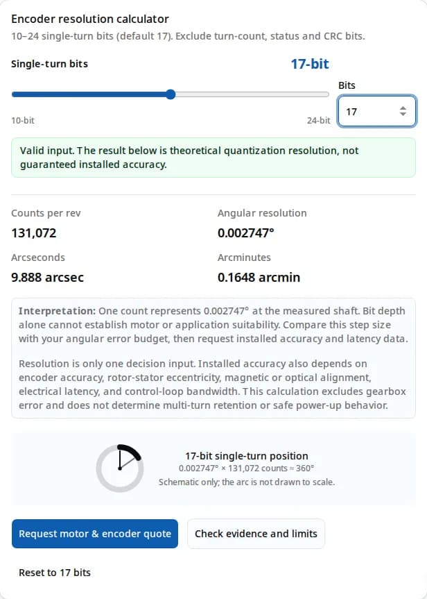
These are arithmetic examples with assumed requirements, not tested product results. Requested accuracy, price, lead time, and protocol performance remain unknown until confirmed for a specific configuration.
Evidence, Source Dates & Limits
These references support the decision logic on this page. They are not a substitute for the final datasheet, drawing, and sample test from the encoder-integrated motor supplier.
| Claim Used | Source | How It Applies | Limit |
|---|---|---|---|
| Compact robot joints can use off-axis magnetic absolute feedback when the ring/readhead geometry fits the motor package. | RLS AksIM-2 absolute magnetic encoder Reviewed September 26, 2026 | RLS positions AksIM-2 as a non-contact off-axis absolute magnetic encoder for limited installation space, with product listings showing up to 20-bit resolution. | Use as an architecture example. Final sizing still depends on ring diameter, readhead gap, shaft runout, temperature, and shielding. |
| Resolution is not accuracy: the AS5048A publishes 14-bit position data and a separate accuracy specification. | Infineon AS5048A product specifications Reviewed September 26, 2026 | The manufacturer lists 16,384 positions per revolution and an accuracy value of 0.5°. The 0.021973° step is calculated as 360/16,384; it is not an accuracy specification. | The product-page accuracy listing is not an installed error bound or a temperature-drift measurement. Confirm datasheet test conditions and assembled-axis measurements. |
| Multi-turn absolute encoders can operate without batteries or gears by harvesting energy from the rotating shaft. | POSITAL IXARC multiturn kit encoder overview Reviewed September 26, 2026 | POSITAL describes multiturn variants with a self-powered counter using Wiegand sensors and an ASIC, without a battery or mechanical counting gears. | This applies to the specified multiturn variants, not every absolute encoder. Confirm turn range, initialization, and power-off motion behavior for the ordered model. |
| Optical absolute encoders are strong candidates for metrology-grade axes, while contamination control remains a design input. | Renishaw RESOLUTE white paper Reviewed September 26, 2026 | Renishaw explains image-based absolute position calculation, error flag behavior, CRC, and contamination response for the RESOLUTE optical system. | Do not treat all optical encoders as fragile or all magnetic encoders as rugged. Compare the exact IP, shock, vibration, and cleanliness ratings. |
| Evaluate sensor processing, frame length, timeout, and controller timing together when budgeting feedback latency. | BiSS Association interface timing overview Reviewed September 26, 2026 | The BiSS Association describes data capture, slave processing time, line-delay compensation, CRC, and a fixed or adaptive timeout that terminates each frame. | A protocol name alone does not establish clock speed or loop rate. Use the exact encoder and controller timing specifications; SSI limits are also implementation-specific. |
| Single-turn angle and multi-turn position solve different measurement tasks. | POSITAL position and velocity measurement guide Reviewed September 26, 2026 | The guide separates orientation within a revolution from measurements that also need the number of completed revolutions. | Machine zero, gearbox ratio, travel limits, and startup validity still need system-level verification. |
Incremental vs. Absolute Feedback
Incremental feedback
Counts motion relative to a reference. A machine may need homing after a power cycle if that reference is lost. Suitable for relative speed or motion tasks when absolute startup position is unnecessary.
Absolute feedback
Reports a coded position within the encoder range. Single-turn angle repeats every revolution. Validate zero offset, startup diagnostics, and any turn-count requirement before enabling motion.
Magnetic vs. Optical Absolute Encoders
Use this comparison as a first-pass architecture screen for an absolute encoder motor. Final selection should use the exact encoder datasheet, motor drawing, and sample test data.
| Feature / Spec | Magnetic Absolute | Optical Absolute |
|---|---|---|
| Mechanism | Magnetic sensing of an on-axis magnet or an off-axis ring | LED and photodetector reading a coded glass/metal disk |
| Industry Examples | AS5048A, RLS AksIM-2 | Renishaw RESOLUTE |
| Resolution Examples | AS5048A: 14 bits; RLS AksIM-2: up to 20 bits depending on configuration. See the linked manufacturer sources. | Model-dependent; confirm the selected scale, diameter, interface, and output format. No universal optical bit range is assumed here. |
| Main Accuracy Drivers | Magnet quality, air gap, centering, stray fields, sensor linearity, temperature, and post-assembly calibration. | Scale/readhead alignment, contamination control, vibration, interpolation error, thermal behavior, and installation stiffness. |
| Latency | Sensor processing plus serial frame time. Some ICs include dynamic angle compensation under specified conditions. | Protocol, frame length, controller timing, and readhead processing determine loop impact. |
| Environmental Tolerance | Often strong in dust, oil, and moisture when package, sealing, and shielding are designed for the application. | Can perform very well in controlled environments; scale and readhead contamination behavior must be reviewed for the exact system. |
| Shock & Vibration | Depends on magnet retention, readhead mounting, PCB support, connector strain relief, and published test rating. | Depends on scale material, readhead mounting, bearing system, protective housing, and published test rating. |
| Best For... | Robot joints, AGVs, Exoskeletons, Harsh environments | CNC machines, Metrology, Semiconductor equipment |
Boundary note: magnetic encoders are not automatically immune to motor flux or external magnetic fields; optical encoders are not automatically unsuitable for industrial use. Check the selected product's environmental, shock, vibration, EMC, and installation requirements.
Selection Matrix by Motor Use Case
| Use Case | Priority | Starting Point | RFQ Evidence |
|---|---|---|---|
| QDD or robot joint motor | Immediate absolute angle, smooth FOC startup, compact packaging | Screen magnetic ring feedback if packaging fits, then size resolution from the error budget and verify installed accuracy and field tolerance. | Ask for single-turn bits, installed accuracy, update rate, protocol, cable exit, IP rating, calibration file, and motor-side vs output-side feedback. |
| AGV / AMR steering or traction wheel | Rugged startup position and repeatable steering angle | Use magnetic absolute feedback when contamination, vibration, and service access dominate over metrology precision. | Ask for shock/vibration rating, sealing, temperature range, connector strain relief, and replacement calibration workflow. |
| Exoskeleton or wearable actuator | Low-speed smoothness, compact stack height, safety state awareness | Use absolute feedback with redundant status where safety architecture requires position confidence after power interruption. | Ask for redundant channel options, power-up position validity, diagnostic flags, torque ripple data, and battery-off behavior. |
| CNC, semiconductor, or optical alignment axis | Metrology-grade repeatability and thermal stability | Evaluate optical or high-grade ring encoders when cleanliness and installation control are available. | Ask for accuracy class, interpolation error, scale material, readhead gap tolerance, contamination behavior, and thermal compensation. |
Prepare your encoder motor RFQ
Send the measured shaft, target accuracy, torque-speed requirements and controller protocol for a configuration review.
Discuss motor and encoder integrationIntegration Risks & Architectural Trade-offs
1. Magnetic Interference (Stray Fields)
In compact outrunner motors, rotor flux, phase current, and nearby magnets can disturb a magnetic absolute encoder if the sensing geometry is not protected. Mitigation: review axial distance, shielding, magnet grade, off-axis ring placement, EMC test results, and post-assembly calibration data.
2. Communication Latency (BiSS-C vs SSI)
Clock frequency alone does not describe feedback latency. BiSS frames include processing and a fixed or adaptive timeout; SSI timing also depends on the selected hardware. Mitigation: budget sensor delay, complete frame time, cable effects, timeout, and controller scheduling from the actual datasheets. Verify timing with the production cable and drive.
3. Resolution Does Not Equal Accuracy
The AS5048A lists 14-bit resolution and an accuracy value of 0.5° separately. Quantization, sensor nonlinearity, mounting error, and temperature effects are distinct error terms. Mitigation: request guaranteed accuracy conditions and an installed error map over the required load and temperature range.
4. Multi-turn Tracking Method (Battery vs Gearless)
If different turn counts represent different machine positions, a single-turn angle cannot recover that distinction after power-off movement. Mitigation: verify the multi-turn range and retention method. POSITAL describes Wiegand-powered counters without counting gears or batteries; a limited-angle output encoder is another option when it makes machine position unambiguous.
5. Integration Cost & Overspecification
Higher bit depth cannot repair mechanical error. Price and lead time are not verified here. Mitigation: compare quotes including calibration, mounting, shielding, controller support, and field replacement. If only relative motion is needed and homing is acceptable, evaluate incremental feedback before adding multi-turn complexity.
RFQ Checklist: Turn the Result Into a Quote
After using the calculator, send these checks with the motor torque-speed requirements so the supplier can quote an encoder configuration rather than a bare resolution number.
| Check | Why It Matters | Ask Supplier For |
|---|---|---|
| Resolution and position word length | The calculator gives quantization only; the controller must also parse the exact single-turn and optional multi-turn frame. | Bits, coding, sign convention, wrap behavior, status bits, and CRC polynomial. |
| Installed accuracy after assembly | Mounting eccentricity, magnet quality, scale alignment, and calibration can dominate nominal resolution. | Accuracy at output shaft, repeatability, calibration method, and expected error map after production assembly. |
| Latency and update rate | A high bit count can still perform poorly if frame time or sensor processing creates phase lag in the motor control loop. | Sensor delay, serial frame time, maximum clock, controller sample rate, and velocity-dependent compensation conditions. |
| Environment and service limits | Magnetic and optical systems fail differently under stray fields, contamination, vibration, temperature, and cable stress. | IP rating, shock/vibration test standard, thermal range, EMC notes, shielding recommendation, and field replacement process. |
Related QDD Motors Pages for the Same RFQ
Use these adjacent pages to keep the absolute encoder motor decision connected to the actual module, winding, and application requirements. This page stays focused on encoder feedback; the links below cover neighboring sourcing decisions.
| Decision Area | Adjacent Page | Use It When... |
|---|---|---|
| Encoder-integrated joint module | Integrated robot joint motor modules | Use when the RFQ needs motor, reducer, encoder, brake option, and driver validated as one package. |
| High-torque motor baseline | High torque motors | Use when the motor winding, torque-speed curve, and feedback format need to be compared before choosing the encoder. |
| QDD actuator architecture | Quasi-direct drive actuators | Use when low-ratio gearing, backdrivability, absolute feedback, and compact packaging are the core trade-off. |
| Application validation path | Robotic arm joint solutions | Use when encoder accuracy, backlash, payload, and safety-state behavior must be tested at the arm level. |
| Hollow shaft integration | Absolute encoder hollow shaft motor sizing | Use when the motor axis must be clear for cables and you need to compare off-axis ring constraints. |
| Production validation plan | QDD Motors quality validation | Use when encoder calibration, inspection records, sample approval, and production traceability must be agreed before launch. |
Frequently Asked Questions
What is the advantage of an absolute encoder on a motor?
An absolute encoder reports an angle within its specified range after startup and validity checks. Avoiding homing also requires a known machine zero and an unambiguous mechanical position. A single-turn motor encoder does not by itself identify the output position through a gearbox.
What bit resolution do I need for a robot joint motor?
Set an allowed quantization step at the measured shaft, then use N = ceil(log2(360 / step in degrees)) as a minimum resolution screen. Reserve separate error budget for installed accuracy, gearbox error, and latency; no bit count alone qualifies a joint.
Does higher encoder resolution always improve motor accuracy?
No. Resolution is the digital step size. The AS5048A product page separately lists 14 bits (a calculated 0.021973° step) and an accuracy value of 0.5°. That accuracy figure is neither a thermal-drift value nor a guaranteed installed error bound. See the linked evidence table for conditions.
Magnetic vs optical absolute encoders: which is better?
Magnetic encoders usually win when compactness, contamination tolerance, and shock resistance drive the design. Optical encoders usually win when metrology-grade accuracy and controlled installation conditions are more important.
Can an absolute encoder replace Hall sensors for motor startup?
Yes, if the controller can use the absolute angle for electrical zero alignment and commutation. The RFQ should include pole pairs, angle offset procedure, update rate, and accepted protocol.
What protocol should I choose for an absolute encoder motor?
Choose a protocol supported by both encoder and controller. For BiSS-C or SSI, check the actual position frame, clock, processing delay, timeout, cable limits, and diagnostics. BiSS-C includes CRC and fixed or adaptive timeout; the protocol label alone does not guarantee a loop rate or price.
Do QDD Motors come with absolute encoders?
QDD motor and actuator configurations can integrate absolute magnetic feedback. The exact encoder layout, motor-side or output-side measurement, and redundancy level should be confirmed against the torque, safety, and package requirements of the project.
What should I send in an RFQ for an encoder-integrated motor?
Send torque-speed requirements, supply voltage, motor diameter and stack limits, target bit depth, required installed accuracy, protocol, cable/connector needs, operating environment, and whether the application needs redundant position feedback.
Should the absolute encoder measure motor-side or output-side position?
Motor-side feedback is useful for commutation and compact packaging. Output-side feedback is better when gearbox compliance, backlash, or joint load accuracy drives the requirement. Many robot joints need the RFQ to specify which angle the controller must trust.
What is the formula behind the resolution calculator?
Counts per revolution equals 2 raised to the bit depth. Degrees per count equals 360 divided by counts per revolution, and arcseconds per count equals degrees per count multiplied by 3,600.
When is a high-bit absolute encoder still the wrong choice?
It can be wrong when installed accuracy, latency, shaft runout, thermal drift, or magnetic interference dominate the error budget. A lower-bit encoder with better calibration and faster transport can outperform a nominally higher-resolution option.
Do I need single-turn or multi-turn absolute feedback?
Single-turn absolute feedback recovers angle within one revolution after power-up. Multi-turn is needed when different revolution counts represent different machine positions and those counts must survive power-off movement. A limited-angle output axis may only need single-turn feedback, while its geared motor shaft may require turn counting. Verify the selected retention method and range.
Inquiry Email
Include target torque/speed, quantity, and delivery location.
Instant Chat
+86 188 5797 1991
Opens a direct WhatsApp thread with the RFQ message prefilled.