
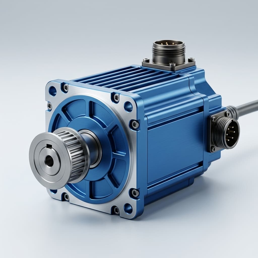
Continuous Torque Derating and Thermal Impedance in Robotic QDD Actuators: A Procurement and Engineering Guide
Compare QDD continuous torque derating, thermal impedance and RMS duty cycles. Use the engineering example and RFQ checklist to request supplier test evidence.
QDD continuous torque derating is a selection constraint: peak torque alone cannot qualify a robot joint. Ask for continuous output torque at your joint speed, worst-case ambient temperature and actual mounting conditions, then compare that rating with the duty cycle's RMS torque. Separately verify peak current, pulse duration, recovery time and winding, rotor and drive temperatures.
For example, a hypothetical actuator rated at 120 N·m peak and 30 N·m continuous would not qualify for a 63 N·m RMS cycle merely because every instantaneous demand stays below 120 N·m. Those are illustrative inputs, not measurements of a QDD Motors product.
This guide gives hardware engineers and procurement teams a method for comparing thermal models, identifying missing supplier evidence and specifying dynamometer acceptance tests before a production purchase order.
Published and reviewed: October 30, 2026. Scope: Global OEM teams integrating QDD actuators into humanoids, quadrupeds, robot arms and exoskeletons. Limitations: The calculations are reproducible engineering examples, not physical test results or product certifications. Cooling, speed, winding resistance, magnet temperature and the inverter can all change the usable rating. The cover shows illustrative motor packaging; the schematic explains heat paths and carries no product performance claim. Published by QDD Motors, an actuator supplier; this is a supplier-authored selection guide.
Share your torque-speed-time trace, ambient range and mounting drawing with our custom motor engineering team, or compare available QDD actuators and OEM motor manufacturing capabilities.
1. The Physics of the Thermal Cliff: Joule Heating in Low-Ratio Actuators
Low reduction can improve backdrivability, but it also requires more motor torque for a given joint torque. The MIT Cheetah actuator paper provides research context for this design trade-off. It does not establish a universal continuous-to-peak ratio for commercial QDD products.
Electromagnetic Torque vs. Copper Losses
For a sinusoidal PMSM with zero d-axis current and negligible reluctance torque, use a consistent current convention:
T_em = 1.5 × p × λ_pm × I_q = K_t × I_q
T_out ≈ K_t × I_q × N × η_gear
P_loss,cu = 3 × I_phase,rms² × R_ph = 1.5 × I_q² × R_ph
Here I_q uses an amplitude-invariant Park transform: at zero d-axis current it equals phase-current peak amplitude, so I_phase,rms = I_q / sqrt(2). R_ph is hot line-to-neutral phase resistance, p is the pole-pair count, λ_pm is magnet flux linkage and K_t must use that same peak-current convention. Never substitute a line-to-line resistance, RMS-based torque constant or DC bus current without conversion.
N is reduction ratio and η_gear is efficiency at the operating speed, load and temperature. At locked output, validate the static torque-current relationship directly; a power-efficiency number does not define stall behavior.
The Ratio-Squared Trade-Off
P_loss,cu ≈ 1.5 × [T_out / (N × η_gear × K_t)]² × R_phFor the same motor, output torque and assumed efficiency, copper loss varies inversely with N². Moving from 8:1 to 16:1 would halve current and quarter copper loss in this restricted calculation. It also doubles motor speed at a fixed joint speed and increases reflected rotor inertia fourfold. Iron loss, gear friction, voltage limits and backdrivability must be checked again; this is not a comparison of two independently designed commercial actuators.
2. Lumped-Parameter Thermal Network: Modeling Thermal Resistance and Impedance
A lumped-parameter thermal network (LPTN) separates winding, stator and housing temperatures. Its resistances must be identified for the actual assembly:
- Winding to stator (
R_th,w-s): Enamel, slot liners, impregnation and voids control the internal hot-spot gradient. - Stator to housing (
R_th,s-h): Fit, adhesive thickness and contact quality affect conduction into the case. - Housing to environment (
R_th,h-a): Air convection, radiation and conduction through the robot link form parallel cooling paths. Use their effective resistance, including the link's ability to reject heat after it warms up.
Steady-State Temperature Rise
For winding-generated heat alone in a simplified series model:
R_th,w-a = R_th,w-s + R_th,s-h + R_th,h-a
T_w = T_ambient + P_loss,cu × R_th,w-a
Iron, inverter and gearbox losses enter different nodes. Multiplying every loss by the entire winding-to-ambient resistance can misrepresent winding temperature. Add heat sources at their physical locations or use a measured assembly model. Hot copper resistance and temperature-dependent torque constant also need to be included in a final rating model.
Thermal Time Constants and Transient Impedance
Resistance describes the steady state; thermal capacitance determines how quickly temperature changes. In a single-node approximation, τ = R_th × C_th and step-response thermal impedance is:
Z_th(t) = R_th × [1 − exp(−t / τ)]
ΔT(t) = P_step × Z_th(t)
R_th and Z_th have units K/W; C_th has units J/K; τ is in seconds. A real joint has several coupled time constants. Fit heating and cooling traces rather than assuming that a short burst test proves continuous capability. Record initial temperature and repeated-pulse recovery conditions.
Worked Derating Example: From Thermal Budget to Output Torque
Assume illustrative, fixed hot parameters: a validated winding limit of 120°C, ambient 40°C, winding-to-ambient resistance 1.0 K/W, phase resistance 0.10 Ω, K_t = 0.40 N·m/A_peak, N = 8 and efficiency 0.95. For this deliberately simplified calculation, represent 10 W of other losses as an equivalent heat input at the winding node.
Allowed copper loss = (120 − 40) / 1.0 − 10 = 70 W
I_q = sqrt[70 / (1.5 × 0.10)] = 21.60 A_peak
T_out ≈ 0.40 × 21.60 × 8 × 0.95 = 65.7 N·m

At 60°C ambient, holding all other assumptions fixed:
Allowed copper loss = (120 − 60) / 1.0 − 10 = 50 W
T_out ≈ 0.40 × sqrt[50 / 0.15] × 8 × 0.95 = 55.5 N·m
The hotter example loses about 15% of its continuous torque. That percentage comes from these inputs; it is not a general ambient derating rule. Reject a calculation with a zero or negative remaining heat budget, and check drive, rotor, gear and speed limits before treating a positive result as feasible.
3. Visualizing the Thermal Network: Heat Flux in a Robotic Joint
The schematic shows a simplified winding-to-housing ladder and parallel environmental heat paths. Temperatures and time constants require measurement; no percentage improvement is implied.
4. Stator Potting, Vacuum Impregnation, and Housing Interface Conduction
Air pockets impede heat conduction inside winding bundles. Resin can improve that path, but the process name alone does not establish the resulting continuous rating.
1. Traditional Dip and Bake Varnish
The wound stator is immersed in varnish and cured. Ask for the resin datasheet, cure schedule and evidence of penetration into the actual slot geometry. Remaining voids and thermal cycling can limit performance; there is no universal torque penalty associated with this process.
2. Vacuum Pressure Impregnation (VPI)
Vacuum and pressure help resin reach winding voids. Request process-control records or representative section inspection; VPI does not guarantee a void-free assembly. Cured conductivity and insulation endurance depend on the selected material and process.
3. Thermally Conductive Filled Epoxy Potting
Filled epoxy can bridge internal gaps, but bond-line thickness, voids, cure shrinkage and thermal expansion remain important. Contact resistance is reduced, not eliminated. Moisture or oil resistance requires separate qualification.
Procurement decision: Compare before/after heat-rise measurements at equal torque, speed, ambient and mounting. A higher resin conductivity does not translate directly into the same percentage torque gain. In a copper-loss-limited model with fixed hot resistance, allowable torque scales approximately with the inverse square root of total thermal resistance.
ΔT_hotspot = T_winding,max − T_sensorRequire a measured sensor-to-hot-spot offset across the intended duty cycle. Potting does not justify assuming a particular offset or raising a trip threshold without validation.
5. Winding Insulation vs. Permanent Magnet Demagnetization Limits
Electrical Insulation Classes
IEC 60085:2007 distinguishes thermal evaluation of insulating materials from complete insulation systems. Classes B (130°C), F (155°C) and H (180°C) describe thermal endurance classifications; they are not automatic firmware trip settings or guarantees of a complete actuator's service life.
Require the assembled insulation system's qualification, applicable temperature-rise method and hot-spot allowance. Potting, adhesive, bearings, encoder, drive electronics or magnets may impose a lower limit. A fixed “life halves every 10°C” rule cannot establish service life without the actual system's thermal ageing data.
Rotor Magnet Temperature Is a Separate Constraint
Magnet flux and coercivity change with temperature. Irreversible demagnetization depends on material, geometry, magnetic load line and demagnetizing current, not just a suffix on the magnet grade. Obtain supplier demagnetization curves at relevant temperatures and check worst-case current, including field weakening if used.
Procurement rule: Validate rotor temperature separately from the winding sensor. A rotor and stator need not have identical temperature ratings; the design must keep each below its own validated limit, accounting for sensor offset, controller delay and fault conditions. Do not infer rotor safety from Class H wire alone.
6. Duty Cycle and Torque Derating Matrix
IEC 60034-1:2026 provides the motor rating and performance reference. It supersedes the 2022 edition. For integrated drives, its scope applies to the motor component; it does not certify the complete robotic joint. Specify the contractual edition and applicable test method with the supplier.
The following rows are procurement screening profiles, not standard-prescribed torque percentages. Record both load and speed: an IEC duty designation alone cannot establish an allowable torque or peak duration.
| Duty / profile | Robotic example | Required cycle definition | Evidence to request | Selection limit |
|---|---|---|---|---|
| S1: continuous duty | Sustained running at a defined joint speed | Constant load long enough to reach thermal equilibrium | Stabilized winding, rotor and drive temperatures on the agreed fixture | Continuous torque at that speed, ambient and mounting |
| S2: short-time duty | One positioning or recovery move | Load duration, starting temperature and rest until cooled | Temperature-time trace and approved pulse current | Supplier-approved duration; no universal peak ratio |
| S3: intermittent periodic duty | Repeated load/rest operation with negligible starting heat | Run time, de-energized rest time and cycle duration | Repeated-cycle temperature maxima after stabilization | Do not treat energized holding as cooling rest |
| S4: intermittent duty including starting | Repeated acceleration, running and rest | Acceleration loss, inertia, load, rest and starts per hour | Current, speed and temperature traces | Starting heat must be included |
| S5: intermittent duty including electric braking | Acceleration, motion, braking and rest | Separate starting, loaded running, braking and rest intervals | Motor heat plus drive and regenerative-bus limits | A braking phase is not thermally equivalent to rest |
| S8: continuous periodic duty with related load/speed changes | Repeated predefined operating points | Every load/speed interval and transition; no de-energized rest | Periodic thermal response and speed-dependent losses | An arbitrary walking gait is not automatically S8 |
| Locked-output holding: application test | Payload holding at a fixed joint angle | Holding torque, rotor angle, duration and initial temperature | Static current distribution and local winding temperatures | Three-phase FOC currents need not be confined to one phase; validate local hot spots |
7. Sizing with Root-Mean-Square (RMS) Torque
RMS torque is a useful copper-heating screen when torque is proportional to current, parameters and efficiency are approximately constant, and the cycle is short relative to the relevant thermal response:
T_RMS = sqrt[Σ(T_i² × t_i) / T_total]
T_total = Σt_i
Practical Walkthrough: Humanoid Knee Joint Gait Cycle
Consider this hypothetical 1.2-second cycle. It is calculation input, not a measured gait or a customer case study:
- Weight acceptance and stance extension: 75 N·m for 0.4 s.
- Push-off: 110 N·m for 0.2 s.
- Swing recovery: 12 N·m for 0.6 s.
Σ(T_i² × t_i) = 75² × 0.4 + 110² × 0.2 + 12² × 0.6
              = 2,250 + 2,420 + 86.4 = 4,756.4 N²·m²·s
T_RMS = sqrt(4,756.4 / 1.2) = 62.96 N·m
T_average = (75 × 0.4 + 110 × 0.2 + 12 × 0.6) / 1.2 = 49.33 N·m
The Sizing Decision
A 50 N·m continuous rating would not pass this screen under equivalent rating conditions. RMS demand is about 26% above that rating, corresponding to about 59% more copper loss if torque constant, efficiency and hot resistance are unchanged. This does not predict a specific failure time.
Screening condition: T_cont,actual ≥ T_RMS × S_thermal
Illustrative project margin: S_thermal = 1.20
Required continuous capability = 62.96 × 1.20 = 75.6 N·m
The 20% margin is an example project requirement, not an IEC rule. The 65.7 N·m thermal-budget example in Section 2 clears the unmodified RMS screen at 40°C but fails this chosen margin; its 55.5 N·m result at 60°C also fails the unmodified RMS screen.
Before approval: Verify the 110 N·m pulse at its actual speed and repetition rate, torque-speed/voltage limits, drive phase current and winding hot spots. A long loaded interval, field weakening, changing efficiency or substantial iron loss requires a current/speed loss model and transient thermal validation rather than RMS torque alone.
8. Supplier Dynamometer Vetting and RFQ Procurement Checklist
Use this checklist to make supplier quotes comparable. Accept calibrated measurements with a documented method; simulation is useful supporting evidence, but cannot alone establish the installed assembly rating.
- Rating and test method: State output torque, speed, duty, standard edition and applicable temperature-rise procedure. Distinguish motor-only evidence from integrated-joint validation.
- Mounting and cooling: Record fixture dimensions/material, contact area, interface material, fastener preload, airflow and enclosure. Confirm the robot link can reject heat after warming up.
- Current and resistance conventions: Record phase RMS versus peak, torque-constant basis, winding connection, line-to-line versus phase resistance, and measurement temperature.
- Sensor and hot-spot mapping: Provide sensor locations, calibration, uncertainty and measured winding hot-spot offset. Include a rotor-temperature estimate validated for the intended current range.
- Ambient boundary: Test or validate derating at the application's worst-case ambient. Do not apply a blanket 10%–15% correction to a room-temperature rating.
- Insulation and potting: Identify the complete insulation system, resin datasheet, cure process and void-control method. Require measured thermal improvement for any claimed torque gain.
- Magnet protection: Request temperature-dependent demagnetization curves and a rotor operating-point assessment. Winding trip settings must include sensor offset and controller delay while protecting every component's limit.
- Thermal model and overload recovery: Request identified resistances, thermal time constants, initial temperatures and repeated-pulse recovery traces for configuring overload protection.
- Integrated drive and mechanical losses: Include inverter, bearing, gearbox and dynamic-seal losses at the required speeds and temperatures. Check bus voltage and regenerative-energy limits separately.
- Sample acceptance: Record cold resistance at a defined reference temperature, then run the agreed continuous load until the agreed thermal-equilibrium criterion is met. Define an observation window and maximum temperature-change rate in the contract; a fixed 60-minute run alone does not prove equilibrium. After cooling to the same reference temperature, compare resistance, back-EMF and friction against agreed tolerances; these checks alone do not prove zero degradation.
Procurement handoff: Send the checklist, load trace and mounting drawing to our OEM motor manufacturing engineering team to define the evidence package for your RFQ.
9. Application Boundaries: Cooling Architectures and Mechanical Alternatives
Passive Conduction to the Robot Chassis
A metal link can provide a conduction path if contact area and interface quality are controlled. Link temperature, external surface area and ambient determine sustained cooling. A large cold fixture can mask an inadequate steady-state heat path. There is no universal 150 W cutoff or universal safe-touch surface temperature; assess material, contact duration and the application's safety requirements.
Forced Convection and Internal Airflow
Moving air can reduce a particular resistance. An internal fan in a sealed housing redistributes heat but still needs an effective external heat-rejection path. Verify acoustic limits, fan failure behavior, contamination control and ingress protection for the actual arrangement.
Liquid Cooling
Consider a cooling jacket when the measured passive heat path cannot meet the duty. State coolant inlet temperature, flow, pressure drop, leak containment and pump-failure protection. Robot mass or a fixed wattage band alone does not establish that liquid cooling is required.
Adjusting the Powertrain Ratio
Under the same-motor assumptions in Section 1, increasing reduction can lower copper loss. It also changes motor speed, reflected inertia, friction and backdrivability. Compare the complete torque-speed duty and thermal model before choosing a higher ratio.
10. Frequently Asked Questions (FAQ)
What is the difference between continuous torque and peak torque?
Continuous torque is sustainable at specified speed, ambient, cooling and temperature limits after thermal equilibrium. Peak torque is an explicitly time-limited operating point. Its starting temperature, duration, repetition and recovery conditions must come from the supplier; there is no universal 1–30 second allowance.
Do QDD actuators always derate more than conventional servomotors?
No. Lower reduction increases the motor torque needed for a given joint load, but winding design, motor size, cooling and efficiency differ between products. Compare validated installed continuous ratings, not gear ratio alone.
How much continuous torque does vacuum epoxy potting add?
There is no universal percentage. Compare total winding-to-ambient thermal resistance and temperature rise before and after the process under matched conditions. Resin conductivity alone does not establish actuator performance.
Can the winding sensor protect the permanent magnets?
Only with a validated relationship between the sensor and rotor temperatures, plus the magnet's operating-point limits. Class H insulation does not establish rotor safety. Assess worst-case current and field weakening separately.
Is RMS torque enough to approve an actuator?
No. It screens copper heating under stated assumptions. Also check peak current and duration, joint speed, voltage, thermal transients, rotor temperature and the installed mounting conditions. Long pulses may exceed a local hot-spot limit even when cycle RMS is acceptable.
How does an aluminum robot link affect continuous rating?
It can improve conduction from the case, but the benefit depends on the interface and the link's steady-state heat rejection. Test the actual mounting or a validated equivalent; do not assume a fixed percentage improvement.
11. Conclusion and Next Steps
Approve a QDD actuator against its installed continuous and transient thermal envelope. A useful RFQ connects four evidence sets:
- Torque, speed and time traces, including holding and recovery.
- Thermal model and measured winding, rotor and drive limits.
- Mounting, enclosure, cooling and worst-case ambient conditions.
- Calibrated heat-rise and repeated-duty validation with agreed acceptance tolerances.
Share these inputs with our OEM motor manufacturing team and custom motor engineering group to discuss a winding, gear ratio and validation plan suited to your joint. Confirm model-specific capabilities and test deliverables in the quotation.
Sources & References
Reference records checked October 30, 2026. IEC catalog records establish publication identity and scope; full standards and the agreed test procedure are needed for clause-level compliance. None of these references validates a QDD Motors product or the illustrative numerical inputs above.
- IEC 60034-1:2026: Rotating electrical machines – Part 1: Rating and performance. Official IEC record. Current edition replacing 2022; for an integrated drive, this standard's scope applies to the motor component, not complete-joint certification.
- IEC 60085:2007: Electrical insulation – Thermal evaluation and designation. Official IEC record. Establishes thermal-endurance evaluation and classification for insulating materials and insulation systems, rather than a complete actuator trip setting.
- P. M. Wensing, A. Wang, S. Seok, D. Otten, J. Lang and S. Kim (2017): Proprioceptive Actuator Design in the MIT Cheetah: Impact Mitigation and High-Bandwidth Physical Interaction for Dynamic Legged Robots. IEEE Transactions on Robotics. MIT Biomimetic Robotics Lab publication record. Research context for low-reduction actuator design; the record confirms bibliographic identity, not the hypothetical thermal parameters used here.
Author

Categories
More Posts
Selecting Frameless Torque Motors for Surgical Robotics: A Procurement and Engineering Guide
Specify frameless torque motors for surgical robotics with procurement checks for cogging torque, thermal limits, hollow bores, and QDD Motors support.
Frameless Torque Motors: The Ultimate Guide for CNC and Automation Integration
Learn how frameless torque motors (stator and rotor sets) are integrated into high-precision CNC machines, robotic joints, and custom automation equipment.
The Hidden Costs of Frameless Motor Integration: A TCO Model for Procurement
Use this frameless motor TCO model to compare kit price, housing, thermal design, QA, and lifecycle risk before issuing a robotics or OEM RFQ.