
AGV Frameless Motor Sizing & Integration Guide
Estimate active stack, phase current and winding temperature. Start with motor-shaft requirements, then check the integration evidence below.
· by QDD Motors
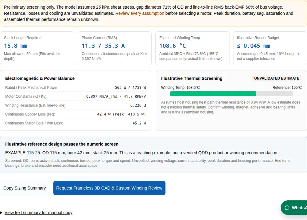
Preliminary screening only. The model assumes 25 kPa shear stress, gap diameter 71% of OD and line-to-line RMS back-EMF 60% of bus voltage. Resistance, losses and cooling are unvalidated estimates. Review every assumption before selecting a motor. Peak duration, battery sag, saturation and assembled thermal performance remain unknown.
Stack Length Required
15.8 mm
Max allowed: 30 mm (Fits available depth)
Phase Current (RMS)
11.3 / 35.3 A
Continuous / instantaneous peak at Kt ≈ 0.397 Nm/A
Estimated Winding Temp
108.6 °C
Ambient 35°C + Rise 73.6°C (155°C comparison only; actual limit unknown)
Illustrative Runout Budget
≤ 0.045 mm
Assumed gap 0.45 mm; 10% budget is not a supplier tolerance
Electromagnetic & Power Balance
- Rated / Peak Mechanical Power:565 W / 1759 W
- Motor Constants (Kt / Kv):0.397 Nm/A_rms · 41.7 RPM/V
- Winding Resistance (Est. line-to-line):0.220 Ω
- Continuous Copper Loss (I²R):42.4 W (Peak: 410.5 W)
- Continuous Stator Core / Iron Loss:45.2 W
Illustrative Thermal ScreeningUNVALIDATED ESTIMATE
Assumes host housing heat path thermal resistance of 0.84 K/W. A low estimate does not establish thermal safety. Confirm winding, magnet, adhesive and bearing limits and test the assembled housing.
Illustrative reference design passes the numeric screen
EXAMPLE-115-25: OD 115 mm, bore 42 mm, stack 25 mm. This is a teaching example, not a verified QDD product or winding recommendation.
Screened: OD, bore, active stack, continuous torque, peak torque and speed. Unverified: winding voltage, current capability, peak duration and housing performance. End turns, bearings, brake and encoder need additional axial space.
View text summary for manual copy
Five decisions before choosing an AGV frameless motor
| Decision | Evidence or calculation | What to do next |
|---|---|---|
| Use a kit when custom integration has value | A bare kit transfers housing, shaft and bearing integration to the OEM. | Compare complete architecture costs, not kit price alone; see the frameless architecture source. |
| Treat torque density as a concept screen | At fixed gap ratio and assumed shear stress, torque scales with D²L. | Use the model assumptions below; obtain a real torque-speed envelope. |
| Budget the complete hot air gap | Manufacturing offset, bearing motion, load deflection and thermal growth accumulate. | Use the selected motor drawing and host stiffness data; do not release machining from this calculator. |
| Qualify retention at temperature | The supplier bonding guide explicitly includes housing thermal effects. | Use the retention comparison and qualify the actual assembled joint. |
| Commission the matched drive and feedback | Kollmorgen documents the effects of phase/feedback mismatch; CiA 402 defines the drive profile. | Follow the inverter-specific procedure; protocol support alone is insufficient. |
References: kit architecture, mounting, commutation. Calculated claims use the explicit assumptions below.
Model equations, assumptions and limits
This is a transparent concept model, not finite element analysis or a validated product selector. Equations reproduce the live tool; empirical constants are assumptions with no calibrated accuracy band. It does not compute bearing deflection, thermal fit, cogging, brake sizing or vehicle traction.
| Output | Equation / convention | Boundary |
|---|---|---|
| Active stack L | T = (π/2) × D_gap² × L × σ; L = 2T / (π × D_gap² × σ) | D_gap and L in metres, T in N·m, σ in Pa. Uniform tangential stress; no saturation model. |
| Mechanical power | ω = 2π × rpm / 60; P = T × ω | Watts. Peak power assumes peak torque at the entered speed; not a guaranteed simultaneous operating point. |
| Torque constant | E_LL,rms = 0.60 × Vdc; Kv = rpm / E_LL,rms; Kt = √3 × 60 / (2π × Kv) | Kv in rpm/V line-to-line RMS, Kt in N·m/A phase RMS. Ideal sinusoidal power balance; winding and inductive voltage drops still require checking. |
| Phase current and copper loss | I_rms = T/Kt; P_cu = 1.5 × I_rms² × R_LL | Balanced star-connected winding with line-to-line resistance. R_LL is a heuristic, not a measured winding. |
| Temperature estimate | T_winding = T_ambient + (P_cu + P_core) × Rθ | Steady state only. Ignores hot resistance feedback, transients and magnet/adhesive limits. |
| Illustrative runout budget | Assumed gap × 0.10 | A screening budget, not a universal tolerance or bearing capacity claim. |
| Assumption | Value / rule | What remains unknown |
|---|---|---|
| Magnetic geometry | D_gap = 0.71 × stator OD; σ = 25,000 Pa | Slot depth, winding fill, saturation and actual torque density. Bore is a reference-design filter, not an electromagnetic geometry model. |
| Line-to-line resistance | Clamp 0.22 × (T_cont/4.5)^0.75 × (48/Vdc) to 0.05–1.2 Ω | Winding turns, conductor size and hot resistance. Scaling is illustrative. |
| Core-loss allowance | 0.08 × continuous mechanical power | Actual no-load, speed-dependent and inverter losses. |
| Thermal resistance | Clamp 0.005/[π × OD_m × L_required,m] to 0.2–2.5 K/W, then multiply by cooling factor | Whole assembly heat path. Available empty depth does not count as active heat-transfer area. |
| Cooling factors | Conduction 1.0; sealed air 2.4; forced cooling 0.6 | Uncalibrated scenario multipliers; not measured thermal performance. |
| Thermal display bands | 130°C caution; 155°C upper comparison | These thresholds do not establish allowable motor temperature or safety. Supplier limits may be lower. |
| Air gap | OD <80 mm: 0.35 mm; <130 mm: 0.45 mm; otherwise 0.55 mm | Assumed display geometry only; obtain motor-specific drawing. |
The Kollmorgen RMS convention reference supports the Kt conversion. Other numeric assumptions above are disclosed modeling choices. The tool updates synchronously; there is no remote calculation or waiting queue.
Four illustrative motor-shaft scenarios
Assumptions and outputs below use the same model as the tool. They are hypothetical motor-shaft cases, not measured vehicles or production duty ratings. Wheel speed requires a wheel diameter and transmission ratio.
| Scenario | Continuous / peak torque | Speed / bus | OD × active stack limit | Bore / ambient / cooling |
|---|---|---|---|---|
| Low-Profile Warehouse AMR Hub (48V) | 4.8 / 15 N·m | 1200 rpm / 48 V | 120 × 28 mm | 36 mm / 35°C / conduction |
| Heavy Pallet AGV Azimuth Turret (48V) | 14 / 42 N·m | 800 rpm / 48 V | 150 × 40 mm | 55 mm / 40°C / conduction |
| Sorting AMR Geared Motor Shaft (24V) | 2.4 / 7.5 N·m | 1800 rpm / 24 V | 90 × 22 mm | 25 mm / 30°C / sealed air |
| Mobile Manipulator Joint 1 Turret (48V) | 1.6 / 5.2 N·m | 2200 rpm / 48 V | 75 × 18 mm | 20 mm / 35°C / conduction |
| Scenario | Required active stack | Continuous power | Continuous / peak phase RMS current | Estimated winding temperature | Numeric reference screen |
|---|---|---|---|---|---|
| Low-Profile Warehouse AMR Hub (48V) | 16.8 mm | 603 W | 12.1 / 37.8 A | 112.9°C — unvalidated | EXAMPLE-115-25 |
| Heavy Pallet AGV Azimuth Turret (48V) | 31.4 mm | 1173 W | 23.5 / 70.5 A | 215.9°C — unvalidated | No match; custom review required |
| Sorting AMR Geared Motor Shaft (24V) | 15.0 mm | 452 W | 18.1 / 56.7 A | 516.9°C — unvalidated | EXAMPLE-90-20 |
| Mobile Manipulator Joint 1 Turret (48V) | 14.4 mm | 369 W | 7.4 / 24.0 A | 90.8°C — unvalidated | No match; custom review required |
For preset 1, the assumed 120 mm OD gives 16.8 mm active stack and 12.1 A RMS continuous phase current. The 112.9°C thermal estimate uses 0.79 K/W. Request winding resistance, a torque-speed curve and an assembled heat test before treating this as a feasible drive. Prepare your winding review request.
Compare complete drivetrain architectures
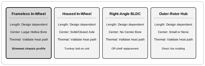
| Architecture | Why consider it | Integration and service tradeoff |
|---|---|---|
| Frameless kit | Custom hollow bore and shared host structure | OEM owns bearings, sealing, thermal path, assembly tooling and qualification. |
| Housed geared wheel drive | Purchased mechanical assembly and service interfaces | Check wheel load/moment ratings, ratio, brake and available mounting envelope. |
| Housed BLDC plus gearbox | Modular procurement and replacement | Couplings, mounts and gearbox consume space and add compliance and loss. |
| Outer-rotor direct drive | Removes gear mesh and ratio selection | Check low-speed torque, external rotor sealing, shock loads and controller ripple. |
For low-volume or schedule-constrained projects, a housed drive may avoid tooling and validation cost. For tightly integrated high-volume designs, compare recurring savings against engineering cost, assembly yield and field replacement effort.
Retention: calculate thermal growth before choosing a joint
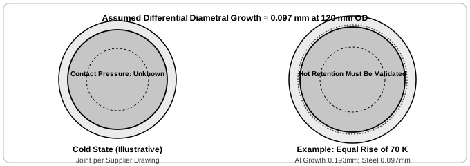
Illustrative equal-temperature example: D = 120 mm, α_housing = 23×10⁻⁶/K, α_stator = 11.5×10⁻⁶/K, ΔT = 70 K. Differential diametral growth is D × (α_housing − α_stator) × ΔT = 0.0966 mm; radial clearance change is half that. These are assumed coefficients, not a material certificate. When housing and stator temperatures differ, calculate each expansion separately.
| Method | Potential value | Unknowns / release check |
|---|---|---|
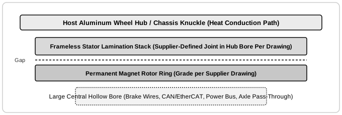
| Engineered interference fit | Direct metal contact without adhesive cure | Fit class alone does not prove positive interference. Calculate tolerance extremes, pressure, lamination stress and hot torque retention. |
| Anaerobic retaining compound, e.g. LOCTITE 648 | Bonded cylindrical joint with controlled clearance | Use current TDS and actual substrate tests. Cure, clearance, surface finish and hot bond strength need qualification; primer is not universally mandatory. |
| Structural epoxy | May suit a qualified bondline or mounting groove | Use the exact adhesive grade and approved cure cycle; do not transfer a recipe between products. |
| Mechanical clamp or retention feature | Can support assembly serviceability and positive retention | Validate clamp stress, fatigue, torque path and assembly repeatability. An axial shoulder alone does not prove torque retention. |
Sources: Kollmorgen bonding examples and Henkel TDS. Neither establishes a universal joint strength, fit class or cure temperature for your motor. Obtain written approval for any rotor heating; a magnetic keeper does not make an arbitrary cure cycle safe.
Wheel overhang: known moments, unknown deflection
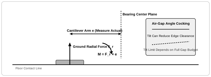
| Assumed radial force Fr | Assumed overhang e | M = Fr × e | Bearing load / air-gap deflection |
|---|---|---|---|
| 1,200 N | 0.038 m | 45.6 N·m | Unknown: need bearing geometry and stiffness |
| 3,200 N | 0.052 m | 166.4 N·m | Unknown: need bearing geometry and stiffness |
| 7,200 N | 0.068 m | 489.6 N·m | Unknown: include housing compliance and shock |
| 14,000 N | 0.085 m | 1,190 N·m | Unknown: include housing compliance and shock |
Check radial, axial and moment loads using the selected bearing manufacturer method; dynamic and static capacity checks differ. Equivalent load is not stiffness. Obtain moment-rotation data, include hub deformation, and calculate edge displacement from tilt and the actual lever arm. There is no universal 0.03° air-gap acceptance limit.
Low-speed ripple: what slot/pole counts can and cannot tell you
| Slots / poles | LCM | Pole pairs / electrical frequency at 1,200 rpm | Evidence needed |
|---|---|---|---|
| 12 / 10 | 60 | 5 / 100 Hz | Measured cogging and loaded speed ripple |
| 12 / 14 | 84 | 7 / 140 Hz | Measured cogging and loaded speed ripple |
| 18 / 16 | 144 | 8 / 160 Hz | Measured cogging and loaded speed ripple |
| 24 / 20 | 120 | 10 / 200 Hz | Measured cogging and loaded speed ripple |
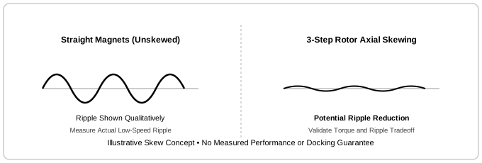
LCM is computed from the integer counts; electrical frequency equals pole pairs × rpm/60. Counts alone cannot establish winding factor, dBA, cogging percentage or docking accuracy. Skew is a design candidate to evaluate against torque loss, manufacturing effort and measured harmonic content. The diagram is qualitative, not test data.
Feedback commissioning: use the matched inverter procedure
| Stage | Required record | Acceptance basis |
|---|---|---|
| Mechanical feedback installation | Encoder drawing, sensing gap, runout and thermal movement | Encoder supplier limits and signal quality over the full rotation |
| Electrical setup | Pole pairs, winding constants, feedback direction and phase order | Motor, encoder and inverter documentation for the actual variants |
| Controlled alignment | Manufacturer routine, configured limits and secured axis | Approved commissioning procedure with unexpected motion controlled |
| Store and verify | Vendor parameter name, firmware version and restart behavior | Bidirectional low-speed check and power-cycle verification per drive manual |
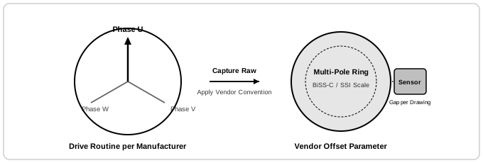
The AKD/AKD2G guide uses MOTOR.PHASE / AXIS#.MOTOR.PHASE. Do not treat 0x3010 as a universal offset. CiA 402 profile support does not determine the calibration routine or a safe injection current.
Make an air-gap budget for the complete assembly
| Feature | What the calculator knows | What to obtain before machining |
|---|---|---|
| Nominal radial gap | Illustrative value by OD band | Motor drawing with radial clearance and operating limits |
| Manufacturing alignment | Assumed 10% gap runout budget | Datum scheme, bore/shaft fits, TIR and offset definitions |
| Bearing and housing deformation | Not modeled | Load spectrum, stiffness curves, preload and hot hub deformation |
| Thermal / dynamic movement | Not modeled | Temperature fields, rotor growth, speed effects and worst-case clearance |
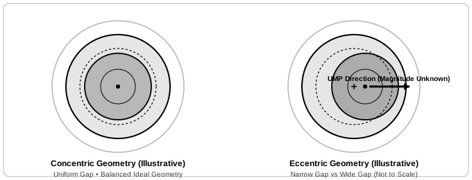
For a simple rigid rotating part, TIR is twice the eccentric radial offset; a loaded multi-part stack needs its own budget. Eccentricity can create unbalanced magnetic attraction, but its force cannot be inferred from runout alone. Confirm hot clearance and full rotation under representative loads.
Validate the whole heat path
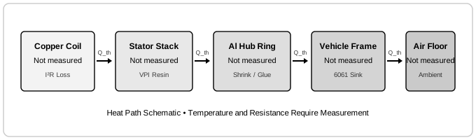
| Interface | Current knowledge | Validation action |
|---|---|---|
| Winding to stator | Unknown winding construction and hot resistance | Obtain sensor location, resistance vs temperature and winding thermal data. |
| Stator to host housing | Depends on fit, bondline and surface condition | Measure interface behavior on representative production joints. |
| Hub to chassis | Depends on geometry and bolted interfaces | Include contact resistance and nearby heat sources. |
| Chassis to ambient | Depends on airflow, enclosure and vehicle operation | Test hot ambient, stationary holding and loaded duty cycles. |
An insulation class does not establish magnet, bearing, adhesive or touch-temperature limits. The 130°C and 155°C display bands are screening comparisons. Use the lowest applicable component limit, measured hotspots and a validated duty-cycle model for release.
Risk review and mitigation evidence
| Risk | Consequence | Mitigation and verification |
|---|---|---|
| Magnetic insertion force | Pinch, rotor impact or insulation damage | Use approved restrained tooling; inspect guides and verify repeatable no-contact assembly. |
| Hot retention loss | Stator slip or lead damage | Calculate hot fit and qualify torque retention, cycling and fatigue. |
| Wheel moment / shock | Gap closure, bearing damage or rubbing | Combine bearing/housing stiffness analysis with loaded hot testing. |
| Drive / feedback mismatch | Unexpected motion, lockup or high loss | Use documented commissioning and verify restart and fault behavior. |
| Integration and service cost | Tooling expense or long repair time | Cost the complete assembly and compare with a replaceable housed drive. |
| Scenario mismatch | High shaft speed mistaken for direct wheel drive | Convert wheel duty using diameter, ratio and efficiency before sizing. |
No failure probabilities, guaranteed life or completed validation results are available for these hypothetical designs.
Illustrative reference designs — not a product catalog
The following hypothetical values make the numeric screen reproducible. They are not verified QDD motor models, availability or supplier ratings. No production datasheet is attached, so none can be released as a selected motor.
| Example ID | Stator OD | Bore | Active stack | Continuous / peak torque | Speed |
|---|---|---|---|---|---|
| EXAMPLE-60-15 | 60 mm | 16 mm | 15 mm | 0.9 / 2.8 N·m | 2400 rpm |
| EXAMPLE-75-18 | 75 mm | 22 mm | 18 mm | 1.8 / 5.6 N·m | 2000 rpm |
| EXAMPLE-90-20 | 90 mm | 30 mm | 20 mm | 2.8 / 8.8 N·m | 1800 rpm |
| EXAMPLE-115-25 | 115 mm | 42 mm | 25 mm | 5.2 / 16.5 N·m | 1500 rpm |
| EXAMPLE-140-35 | 140 mm | 60 mm | 35 mm | 12.5 / 38 N·m | 1200 rpm |
| EXAMPLE-170-45 | 170 mm | 78 mm | 45 mm | 26 / 78 N·m | 950 rpm |
Every displayed match must satisfy OD, bore, active stack, continuous torque, peak torque and speed simultaneously. Winding voltage, current limits, end-turn depth and peak duration remain unverified; no match leads to custom sizing.
Assembly preparation and release checks
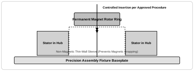
| Phase | Preparation | Release evidence |
|---|---|---|
| Housing and retention | Approved joint drawing, surface preparation and fit or bond process | Dimensional inspection and qualified retention process |
| Rotor insertion | Restrained alignment fixture and supplier-approved nonmagnetic guides | No contact damage; guides removable without contaminating the gap |
| Bearing and rotor location | Specified preload, axial retention and fastener procedure | Rotation, clearance and assembly inspection records |
| System test | Feedback, thermal sensing, seals and external brake integration | Hot loaded clearance, duty-cycle performance and fault testing |
Do not use arbitrary press force, sleeve thickness, insertion speed or cure temperature from a generic guide. Magnetic forces and component limits vary by kit.
Sources, dates and what each source actually supports
Sources reviewed November 1, 2026. Public documentation supports the limited claims stated below; it does not validate this model or any QDD product rating. Manufacturer documents are examples for their own equipment. Standards scope pages are not the full requirements.
| Source | Supports | Does not establish |
|---|---|---|
| Kollmorgen — What is a Frameless Motor? | Explains the stator/rotor kit and its integration into host mechanics. | General architecture; supplies no QDD dimensions or performance ratings. |
| Kollmorgen — Bonding with Structural Adhesives (2017) | Shows mounting alternatives and a KBM bonding example with model-specific clearances and thermal considerations. | KBM examples cannot set tolerances or cure temperatures for an unspecified motor. |
| Henkel — LOCTITE 648 technical data sheet, May 2021 | Documents cylindrical retention, test substrates and how cure depends on joint clearance and temperature. | Coupon data is not assembled motor torque capacity; qualify the actual substrate, finish, bondline and hot joint. |
| Kollmorgen — Establishing Commutation for AKD/AKD2G (2021) | Explains phase/feedback polarity and identifies MOTOR.PHASE and AXIS#.MOTOR.PHASE for those drives. | Vendor procedure only. Do not apply its parameters or current settings to other inverters. |
| CAN in Automation — CiA 402 drive profile | Describes drive states, operating modes and optional functions. | Profile conformance does not validate winding configuration, commutation calibration or motor safety. |
| Kollmorgen — PicoDAD-SN manual, §9.8.6, p.53 (2005) | Gives the RMS convention conversion: torque constant equals voltage constant in V/1000 rpm multiplied by 16.55. | A convention reference, not winding data for this calculator. Real datasheets may use peak, RMS or phase quantities. |
| ISO 3691-4:2023 — Driverless industrial trucks | Official scope covers safety requirements and verification for driverless trucks and their systems. | Public scope only; full requirements require the standard and vehicle risk assessment. A draft revision is under development. |
Turn the preliminary result into a supplier review
| Send | Ask the supplier to return |
|---|---|
| Input summary and torque-speed-time duty | Validated continuous envelope, peak duration and current limits |
| Minimum / maximum loaded bus and inverter limits | Matched winding data: Kt, Ke, hot R, inductance and voltage headroom |
| Complete radial and axial packaging, bore and wheel loads | Assembly CAD, tolerances, bearing/moment checks and installation procedure |
| Ambient, heat path, sealing, feedback and braking needs | Thermal test boundary, sensors, assembly component limits and unknowns |
Start by copying the live sizing summary. Mark missing measurements as unknown so they can be resolved before selecting hardware.
Inquiry Email
Include target torque/speed, quantity, and delivery location.
Instant Chat
WhatsApp Engineering Support
Opens a direct WhatsApp thread with the RFQ message prefilled.
Frequently asked selection and integration questions
What is an AGV frameless motor?
A stator and rotor kit integrated into the vehicle structure. The OEM supplies bearings, shaft, housing and feedback. See the Kollmorgen architecture reference below; no universal package saving is assumed.
Does this tool select a production motor?
No. It screens an illustrative geometry and estimates electrical and thermal quantities. EXAMPLE codes are hypothetical teaching designs, not verified QDD catalog products. Request a supplier drawing and torque-speed curve before selection.
Should I enter wheel torque or motor torque?
Enter motor-shaft torque and speed. For a geared drive use motor torque approximately equal to wheel torque divided by ratio and efficiency, and motor speed equal to wheel speed multiplied by ratio. Include acceleration and losses in the requirements.
Does active stack length equal installed axial length?
No. Add winding end turns, rotor hub, bearings, seals, encoder and brake. A stack that fits can still produce an assembly that is too deep.
How accurate is the winding temperature?
It is an unvalidated concept estimate based on assumed resistance, loss and cooling factors. It does not predict transient peaks, magnet temperature or safe continuous operation. Measure the complete assembly and obtain supplier thermal data.
Does peak torque mean a 30-second rating?
No duration is modeled. Peak current, saturation, magnet demagnetization and the duty cycle must be checked against supplier curves. Do not treat an instantaneous estimate as an S2 duty rating.
What happens if no reference design fits?
The tool explicitly reports no match. Increase available size, reduce requirements, consider a gearbox or send the current summary for custom sizing. It never substitutes an incompatible design.
What air-gap runout should I specify?
Use the selected motor drawing and a complete tolerance and deflection budget. The tool uses an illustrative gap and a 10% screening budget; these are not production tolerances. TIR and radial offset are different measurements.
How does housing expansion affect retention?
Compare housing and stator diameter changes at their respective temperatures. The worked example uses assumed coefficients and equal temperature rise. Actual gradients, fit tolerances, coatings and bondline behavior require joint validation.
Is a cross-roller bearing always the best option?
No. Compare moment rigidity, shock rating, limiting speed, friction, lubrication and cost against paired angular-contact bearings. Neither vehicle mass nor an equivalent-load calculation establishes air-gap deflection without stiffness data.
Can I heat a rotor or cure adhesive at 120°C?
Only use a supplier-approved assembly process. Magnet grade, magnetic circuit, adhesive and insulation may have different limits. There is no universal safe 120°C threshold, and a keeper alone does not qualify a cure cycle.
Is 0x3010 a standard commutation offset?
Do not assume that address. Use the actual inverter manual and firmware revision. The cited Kollmorgen guide names MOTOR.PHASE for AKD and AXIS#.MOTOR.PHASE for AKD2G; other drives differ.
Can I inject a fixed current vector to align any motor?
Use the drive manufacturer commissioning routine with the axis secured against unexpected motion, suitable current limits and working feedback. A generic current recipe is not a commissioning procedure.
Does a high slot/pole LCM guarantee smooth docking?
No. LCM is a geometry descriptor. Magnet shape, slot openings, skew, control tuning, encoder error and drivetrain compliance affect ripple. Request measured cogging and loaded low-speed speed-ripple traces.
Does 48 V automatically make the drive SELV?
No. Nominal battery voltage alone cannot establish the system classification. Charging voltage, transients, isolation and the complete electrical architecture must be evaluated. Phase current also depends on winding constants and speed.
Are braking and ingress protection included?
A bare kit provides neither a vehicle holding brake nor an enclosure IP rating. Design and verify these at assembly level, including brake release wiring, stopping behavior, seals and thermal effects.
When is a housed geared motor preferable?
When purchased load ratings, quick replacement and shorter integration effort outweigh custom packaging gains. Compare total engineering, tooling, qualification and service costs, not just kit prices.
What should I send in an RFQ?
Send the input summary, full torque-speed duty including peak duration, minimum and maximum bus voltage, complete assembly envelope, load and moment cases, cooling boundary, feedback, brake and sealing requirements. Ask the supplier to identify unknowns and provide validated curves.