Size your absolute encoder ring for a hollow shaft motor. Estimate required dimensions and assess off-axis magnetic, optical, and capacitive feasibility.
Public source check: July 28, 2026. See the evidence table below for source links, assumptions, and limits.
The encoder decision starts with the physical motor package: the center bore must stay open, while the encoder ring, readhead, connector, bearings, and cable exit all compete for radial and axial space.
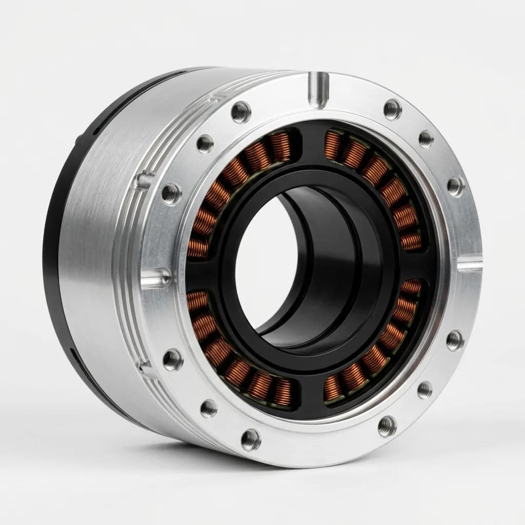
| Technology | Runout Tolerance | Stray EMI/Magnetic Immunity | Typical Accuracy | Best Fit |
|---|---|---|---|---|
| Magnetic ring | Usually the most forgiving start point, but accuracy falls with eccentricity and stray fields. | Vendor-specific. Request immunity limits and installed test data near the motor stator. | Published resolution can be high; installed accuracy depends on ring, readhead, calibration, and bearing runout. | AGVs, industrial robots, compact hollow-shaft joints, dirty environments. |
| Optical ring | Can support very high accuracy when axial gap, radial runout, and contamination are tightly controlled. | Not affected by motor magnetic flux, but vulnerable to contamination and mechanical contact. | Best for high precision systems when the supplier datasheet supports the actual ring diameter and mounting stack. | Metrology axes, clean gimbals, inspection equipment, sealed high-end joints. |
| Capacitive hollow encoder | Designed for ring/hollow formats where whole-circumference sensing can reduce local mounting error. | Often selected for EMI and shock concerns; verify the exact model against the motor environment. | Model-specific. Use vendor-published installed accuracy, not only bit count, as the decision number. | Aerospace, surgical robotics, defense actuators, high reliability compact modules. |
Accuracy language is intentionally installation-based: public datasheets often quote resolution, but the motor buyer needs installed error over the assembled hollow shaft.
| Claim Used | Source | How It Applies | Limit |
|---|---|---|---|
| Hollow shaft BLDC motors typically require off-axis absolute encoders because the central axis is occupied by cables, optics, or cooling lines. | RLS AksIM-2 off-axis magnetic encoder Reviewed July 28, 2026 | RLS positions AksIM-2 as a non-contact off-axis absolute magnetic encoder for limited installation space, with public product listings describing up to 20-bit resolution and ring IDs up to 68mm, plus custom larger rings. | Do not assume every bore has the same resolution or accuracy. Confirm the selected ring ID/OD, readhead location, stray-field immunity, and installed error budget. |
| High-resolution optical rings are viable for hollow shafts but demand strict environmental sealing and precise alignment. | Renishaw RESOLUTE absolute optical encoder Reviewed July 28, 2026 | Renishaw documents image-based absolute position calculation, CRC checking, error flags, and signal checks that help detect contamination or invalid readings. | The linked paper supports safety and signal integrity behavior, not a universal air-gap number. Use the exact readhead/ring datasheet for alignment and contamination limits. |
| Capacitive hollow-shaft encoders can be a strong fit where magnetic immunity, shock, and eccentricity tolerance matter more than lowest component cost. | Netzer Precision Electric Encoders Reviewed July 28, 2026 | Netzer publishes absolute rotary encoder families with ring/hollow formats, model-specific accuracy claims, and specifications for shock, vibration, and environmental resistance. | Treat vendor accuracy as model-specific. Verify the chosen ring size, electronics package, protocol, lead time, and qualification burden. |
| Absolute encoder protocol choice affects safety diagnostics and how quickly the controller can trust position at startup. | BiSS-C unidirectional protocol specification Reviewed July 28, 2026 | The BiSS-C protocol documentation covers frame structure, CRC handling, and serial transfer concepts used by many industrial absolute encoders. | Protocol support does not prove mechanical fit. Match protocol, cable length, controller input, and safety diagnostics separately from encoder geometry. |
The calculator deliberately separates quantization from installed accuracy. Counts per revolution and angular step are useful, but they do not include eccentricity, thermal growth, interpolation error, readhead mounting, or drive-side sampling.
Use the generated encoder architecture as the first filter, then convert it into a supplier evidence request. This keeps the page focused on the same keyword goal: selecting an absolute encoder hollow shaft motor, not just reading an encoder datasheet.
| Budget Item | Unit | Calculator Assumption | Evidence Needed for RFQ |
|---|---|---|---|
| Clear bore | mm | Tool input value | State usable through-bore after insulation, wire bundle, sleeve, or slip-ring clearance. |
| Estimated encoder ring OD | mm | Bore + 16 mm first-pass allowance | Replace with the exact encoder drawing before ordering tooling or housings. |
| Radial runout at ring radius | mm TIR | Not calculated by bit depth | Provide bearing runout, shaft tolerance, and expected thermal growth at operating temperature. |
| Axial air gap / readhead offset | mm | Vendor-specific | Use selected readhead datasheet and assembly fixture capability, not a generic value. |
| Installed angular error | deg or arcsec | Quantization only from calculator | Add quantization, eccentricity, interpolation, calibration residuals, and controller sampling error. |
| Risk | Impact | Mitigation |
|---|---|---|
| Runout or eccentricity exceeds encoder tolerance | Startup position is available, but installed accuracy is worse than the bit count implies. | Request installed accuracy over one revolution and measure TIR on the final bearing stack. |
| Motor stray field corrupts magnetic ring readings | Position words can be noisy around high torque or thermal saturation points. | Ask for stray-field immunity data, add shielding distance, and test at peak current. |
| Readhead and cable exit collide with hollow-shaft routing | The motor fits in CAD but fails assembly or service bend-radius requirements. | Share cable bundle diameter, connector location, and minimum bend radius in the first RFQ. |
| Protocol and controller diagnostics are underspecified | The encoder is mechanically correct but not accepted by the drive firmware. | Specify BiSS-C, SSI, SPI, or CANopen needs, CRC handling, update rate, and startup behavior. |
| Input Pattern | Tool Direction | Engineering Decision |
|---|---|---|
| 25 mm bore, 17-bit target | Off-axis magnetic ring encoder | Good first shortlist for compact robot joints if shielding and bearing runout are controlled. |
| 70 mm bore, 18-bit target | Large-bore magnetic or optical ring | Expect custom ring drawings and a supplier review of runout, ring OD, and readhead packaging. |
| 35 mm bore, 21-bit target | Optical ring encoder | Use only when the joint can hold alignment and contamination limits through production assembly. |
| 45 mm bore, high shock and EMI | Capacitive hollow encoder review | Worth evaluating when reliability and immunity justify higher encoder cost and qualification effort. |
| RFQ Field | Include This Detail |
|---|---|
| Mechanical envelope | Bore ID, allowed ring OD, available axial depth, readhead mount surface, and cable route. |
| Motion and accuracy target | Resolution bits, installed accuracy target, allowable startup error, speed, acceleration, and duty cycle. |
| Environment | Operating temperature, dust/liquid exposure, shock, vibration, sterilization or washdown needs. |
| Electrical interface | Protocol, voltage, update rate, cable length, grounding plan, CRC/error handling, and controller model. |
| Validation plan | Runout measurement, stray-field test at peak current, thermal drift check, and final calibration method. |
| Use Case | Priority | Recommendation | RFQ Action |
|---|---|---|---|
| Robotic arm joint (hollow for cables) | Large clear bore, reliable commutation, absolute position on startup | Off-axis magnetic absolute encoder (17-19 bit). | Ask for bore size, runout tolerance, and stray magnetic field shielding. |
| Pan/Tilt security camera or LiDAR | Smooth low-speed motion, slip-ring integration | Medium-resolution magnetic ring encoder. | Focus on bearing friction, concentricity, and thermal stability. |
| Surgical robotics / Aerospace actuators | Immunity to EMI, high shock tolerance, high accuracy despite bearing play | Capacitive absolute encoder (18-20 bit). | Verify axial depth constraints and required accuracy specs (e.g., < 0.015°). |
| High-end gimbal / Metrology alignment | Metrology-grade precision, zero backlash | Optical ring absolute encoder (20+ bit). | Require cleanroom assembly, IP-rated housing, and mapping of installation error. |
| Next Page | Why It Matters |
|---|---|
| Hollow shaft joint motors | Use when the main constraint is through-bore packaging. |
| Robot joint modules | Use when the encoder must be sourced with brake, bearing, and controller integration. |
| QDD actuators | Use when torque density and integrated BLDC actuator packaging are the top concern. |
| Robotic arm joint solutions | Use for application-level joint sizing and production trade-offs. |
| Quality process | Use when supplier validation, inspection, and test documentation drive the buying decision. |
Because the center of rotation is hollow (for routing cables, light, or air), a standard on-axis encoder IC cannot be used. Instead, an off-axis "ring" encoder (magnetic, optical, or capacitive) must be mounted around the bore.
It depends on the exact encoder family, ring diameter, bearing stack, and mounting fixture. Treat runout as an RFQ input and ask suppliers for installed accuracy at the final ring radius.
They can be more challenging to align. Because the reading happens at a large radius, any mechanical runout or eccentricity directly translates to angular error. However, a well-calibrated large ring can achieve very high resolution.
Use bore plus roughly 16mm only as a first-pass package estimate. The final number must come from the selected encoder ring OD, readhead footprint, connector exit, and assembly clearance.
No. It is a first-pass shortlist that converts bore and bit depth into likely encoder architecture, counts per revolution, angular step, and RFQ checks.
Bit depth gives quantization step. Installed accuracy also includes eccentricity, interpolation error, calibration residuals, thermal growth, bearing runout, controller sampling, and noise.
Choose optical when high installed accuracy is more important than contamination tolerance and when the mechanical stack can hold the supplier air-gap and alignment limits.
Choose capacitive when EMI, shock, vibration, or eccentricity tolerance has more value than lowest component cost or broad commodity availability.
Send bore ID, allowed ring OD, axial depth, target resolution, installed accuracy target, runout estimate, environment, protocol, controller type, and validation expectations.
Yes, if the encoder and controller protocol provide absolute position and the system validates CRC, error flags, or equivalent diagnostic data before enabling motion.
Assembly validation is often the hidden cost. Large rings can need custom fixtures, calibration, runout measurement, and environmental testing before production release.
Compare installed accuracy at your ring size, not only headline resolution. Then check air gap, runout, protocol, temperature, shock, vibration, lead time, and calibration support.
Bring your required bore size, torque curve, and absolute encoder constraints. Our engineering team will help you configure a complete, integrated robot joint motor.
Inquiry Email
Include target torque/speed, quantity, and delivery location.
Instant Chat
+86 188 5797 1991
Opens a direct WhatsApp thread with the RFQ message prefilled.