
Absolute Encoder Robot Actuator
Calculate theoretical angular resolution and compare single vs dual feedback choices for robotic joint actuators.
Published · Reviewed
Input
10-24 bit absolute position word
Output
Counts per revolution and theoretical angular step
Next step
Review architecture (Single vs Dual Encoder)
Input
10-24 bit absolute position word
Output
Counts per revolution and theoretical angular step
Next step
Review architecture (Single vs Dual Encoder)
How the Calculator Gets the Result
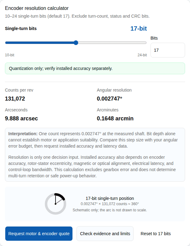
Ideal single-turn quantization
counts per revolution = 2N
degrees per count = 360° / 2N
arcseconds per count = 1,296,000 / 2N
Example: 17 single-turn bits
217 = 131,072 counts/revolution; the ideal step is 0.002747° or 9.888 arcseconds per count (rounded).
This is digital quantization at the measured shaft, not a promise of encoder accuracy or robot-joint accuracy. It excludes multi-turn data, transmission error, mounting, and control delay.
Key Takeaways for Robot Actuators
- Position at Power-Up: An absolute reading can remove a reference move when its measured axis and turn range meet the application requirements. It does not, by itself, make startup or emergency-stop recovery safe.
- Safety Is System-Level: Required performance levels come from the application risk assessment. Encoder count or placement alone cannot establish a PL or Category; validate the complete safety function.
- Multi-Turn Retention: Battery-backed and energy-harvesting multi-turn designs have different service and retention constraints. Specify the required behavior while unpowered.
- QDD Simplification: Low-ratio QDD designs can make motor-side feedback sufficient for some control targets. Verify output error, compliance, and backdrivability on the chosen actuator.
- Hollow Shaft Routing: When a through-bore is needed, compare ring or off-axis encoder layouts against bore size, runout, air gap, and cable clearance.
Public source check: October 7, 2026. See the evidence table below for source links, assumptions, and limits. Reviewed by QDD Motors Engineering Team for robotic actuator RFQ use.
Evidence, Source Dates & Limits
These references support the trade-offs below. Application-specific requirements still need confirmation against the selected actuator and control system.
| Claim Used | Source | How It Applies | Limit |
|---|---|---|---|
| A load-side encoder can measure joint output after drivetrain elasticity and transmission error; the need depends on the control and accuracy target. | Robust design of independent joint control of industrial robots with secondary encoders Reviewed October 7, 2026 | The study analyzes joint-side position feedback and drivetrain elasticity in robot joint control. An output encoder provides a measurement after the transmission, while a motor encoder measures before it. | A second encoder does not itself compensate for compliance or detect a hazardous condition; control logic, diagnostics, calibration, and the application safety design determine those outcomes. |
| ISO 13849-1 sets general design principles for safety-related control-system parts; the required performance level is application-specific. | ISO 13849-1:2023 — General principles for design Reviewed October 7, 2026 | ISO states that the standard does not specify the safety functions or required performance levels (PLr) for particular applications. | Two encoders, a safety-rated encoder, or a safety communication profile alone do not establish a system PL or Category. Validate the complete safety function and its components against the application risk assessment. |
| Some commercial multi-turn encoders use Wiegand energy harvesting to count rotations while unpowered. | POSITAL IXARC absolute multiturn encoder Reviewed October 7, 2026 | POSITAL identifies this product as a multiturn encoder with a self-powered magnetic pulse counter and no battery or gear; its product page also lists a Wiegand sensor test function. | This is one manufacturer and model family, not a property of every absolute encoder. Verify the selected model’s turn-count range, unpowered-motion behavior, temperature range and maintenance guidance. |
| For industrial robot applications, safety requirements cover cell integration and operation; position feedback alone does not make restart or emergency-stop recovery safe. | ISO 10218-2:2025 — Industrial robot applications and robot cells Reviewed October 7, 2026 | The standard addresses integration, commissioning, operation, and maintenance of industrial robot applications and cells. | ISO 10218-2:2025 excludes medical, healthcare and public-access service robots. Confirm the applicable sector standard and risk assessment for those systems. For any application, an absolute reading may remove a homing step only when the measured axis, turn range, retained reference and restart procedure support it; it is not permission to resume motion. |
| An off-axis magnetic encoder can preserve a central bore when the encoder ring and readhead fit the actuator geometry. | RLS AksIM-2 absolute magnetic encoder Reviewed October 7, 2026 | RLS describes AksIM-2 as an off-axis hollow-ring encoder, lists resolution up to 20 bits, and specifies immunity to external magnetic fields for this product. | Use as one product example. Its field-immunity claim does not establish another encoder’s limits or the integrated actuator accuracy; confirm ring diameter, readhead gap, runout, temperature, and application fit. |
| Encoder and controller timing contribute to feedback delay; a safety communication profile is distinct from ordinary position transport. | BiSS Safety profile overview Reviewed October 7, 2026 | BiSS describes BiSS Safety as a profile using redundant position words, CRC checks, and a sign-of-life counter. Actual loop delay also includes the sensor, frame length, controller, and drive. | Neither a protocol name nor its clock rate establishes achieved loop bandwidth or system safety. Confirm end-to-end timing and the certified configuration for the selected hardware. |
Single vs. Dual Encoder Architectures
These are illustrative feedback layouts. Sensor placement does not certify a safety function or guarantee output accuracy.
Selection Matrix by Robot Actuator Type
| Robot Application | Control Priority | Architecture Recommendation | RFQ Needs |
|---|---|---|---|
| Collaborative Robot (Cobot) Arm Joint | Validated safety functions and a defined restart or recovery procedure | Set the required performance level from the application risk assessment. Select encoder feedback and diagnostics as part of the validated safety-related control system; dual position sensors alone do not establish PL or Category. | Ask for the safety manual, certified configuration, diagnostic coverage, response time, power-up validity, and evidence for the complete safety function. Specify multi-turn retention only if the joint range requires it. |
| Quadruped / Legged Robot Hip or Knee | High shock tolerance, low latency for impedance control, compact package | Compare motor-side and output-side feedback against the transmission compliance, joint error budget, and controller design. A low-ratio QDD may make motor-side feedback sufficient for some applications, but this must be validated on the selected actuator. | Set shock and vibration limits from the robot environment; request sensor delay, full-frame timing, controller sample rate, temperature range, and supported interface details. |
| AGV / AMR Steering Module | Rugged startup position and repeatable steering angle | Choose sensing and retention for the steering range, power-off movement, vibration, contamination, and moisture exposure expected in the vehicle. | Define ingress protection from the installation environment; ask for shock/vibration ratings, connector strain relief, power-off turn retention, and replacement interval for any battery-backed option. |
| Surgical or High-Precision Robot Actuator | Metrology-grade repeatability and thermal stability | Compare optical and magnetic ring encoders against the specified system accuracy, repeatability, installation tolerance, contamination range, and thermal behavior. Encoder type alone does not determine installed accuracy. | Ask for system accuracy, interpolation error, temperature drift, contamination limits, and installation tolerances. |
Integration Risks & Architectural Trade-offs
1. Required PL and Safety Architecture
The required PLr depends on the application risk assessment. A second encoder can add output feedback, but sensor count or a position discrepancy does not by itself provide diagnostic coverage or a safe stop. Mitigation: Specify the safety function and request evidence for the complete sensor, drive, logic, and stopping path, including configuration and response time.
2. Multi-Turn Memory: Battery vs Battery-less
Some multi-turn encoders rely on a battery to retain turn count while unpowered; energy-harvesting designs have device-specific operating limits. Mitigation: Confirm power-off motion behavior, retention range, temperature limits, service life, and battery replacement interval for the chosen design.
3. Feedback Timing and Safety Communication
Sensor delay, data framing, filtering, and controller scheduling all contribute to feedback latency. BiSS-C position transport is distinct from the BiSS Safety profile; neither protocol name alone sets achieved loop timing or validates a safety function. Mitigation: Derive a timing budget from the control and safety requirements, then confirm end-to-end timing and the exact certified hardware configuration with the supplier.
4. Magnetic Flux Interference
Encoder susceptibility and allowable external fields depend on the selected sensing design and mounting. Check the manufacturer's immunity specification against the field at the installed sensor position. Mitigation: Request field-immunity and system- accuracy data for the selected sensor, then validate the integrated actuator across the relevant motor-current and temperature range.
5. Hollow Shaft Constraints
Compare encoder layouts by the required bore diameter, ring dimensions, readhead space, installation tolerances, and available cable clearance. Mitigation: Verify the selected ring and readhead envelope against the actuator drawing before release.
RFQ Checklist: Sourcing the Actuator
Send these checks to the supplier when requesting a quote for an absolute encoder robot actuator to ensure the feedback meets control requirements.
| Check | Why It Matters | Ask Supplier For |
|---|---|---|
| Motor-Side vs. Output-Side | Gearboxes introduce backlash, hysteresis, and compliance. The controller needs to know which side of the transmission the encoder is measuring. | Is the absolute encoder on the motor shaft or after the reducer? Does the actuator support dual encoders? |
| Resolution and position word length | The calculator gives quantization only; the controller must parse the exact single-turn and optional multi-turn frame. | Bits, coding, sign convention, wrap behavior, status bits, and CRC polynomial. |
| Latency and update rate | Position word length, frame format, sensor processing, filtering, and controller scheduling contribute to end-to-end feedback delay. | Sensor processing delay, full-frame time, filtering delay, controller sample rate, and timing variation. |
| Hollow Shaft Diameter | Robot joints often require through-routing of power and communication cables to distal links. | Inner diameter of the actuator and maximum cable bundle size it can accommodate without interference. |
Related QDD Motors Pages
Use these adjacent pages to navigate the architecture choices between QDD, high-torque BLDC, and fully integrated modules.
| Decision Area | Adjacent Page | Use It When... |
|---|---|---|
| Encoder-integrated joint module | Integrated robot joint motor modules | Use when the RFQ needs motor, reducer, encoder, brake option, and driver validated as one package. |
| QDD actuator architecture | Quasi-direct drive actuators | Use when low-ratio gearing, backdrivability, absolute feedback, and compact packaging are the core trade-off. |
| General absolute encoder BLDC motor | Absolute encoder BLDC motor | Use when reviewing general absolute encoder motor specifications outside of a full robotic actuator context. |
| Quasi Direct Drive Robotics | Absolute encoder quasi direct drive motor | Use when investigating proprioceptive torque control, impedance control, and legged robotics requirements. |
| Hollow shaft integration | Absolute encoder hollow shaft motor | Use when the motor axis must be clear for cables and you need to compare off-axis ring constraints. |
Frequently Asked Questions
Why do robot actuators need absolute encoders?
An absolute encoder reports position without first counting incremental pulses from a reference move. It can remove a homing step only if the encoder measures the relevant axis, its single-turn or multi-turn range covers the application, and the reference remains valid. Startup and emergency-stop recovery still need a validated application procedure; an absolute reading alone does not make motion safe.
Should the absolute encoder be on the motor side or output side?
A motor-side encoder measures before the transmission and is commonly used for motor control. An output-side encoder measures the joint after the transmission, so it observes output motion that a motor-side sensor cannot directly measure. Dual feedback can be useful when the control or accuracy target requires it, while motor-side feedback may suffice for some low-ratio QDD designs. Choose from the actuator mechanics and control requirements; neither arrangement guarantees a safety rating.
What bit resolution is typical for a robot joint actuator?
There is no universal bit-depth target. Start with the joint error budget and required control behavior, then compare the theoretical quantization with the encoder accuracy, repeatability, transmission error, latency, and controller capabilities stated by the supplier. More bits alone do not guarantee better installed accuracy or smoother torque.
Does the calculator show my final robot joint accuracy?
No. The calculator shows quantization (the smallest digital step). Actual robot joint accuracy is degraded by gearbox backlash, mechanical compliance, bearing runout, sensor nonlinearity, and thermal expansion.
What is the impact of encoder latency on robot actuators?
Sensor processing, frame transmission, filtering, and controller scheduling all contribute to feedback delay and can constrain control bandwidth. Compare end-to-end timing with the control-loop budget. BiSS-C is a position interface; BiSS Safety is a separate safety profile. A protocol label by itself does not establish achieved latency or a safety rating.
Can absolute magnetic encoders handle the magnetic flux from the actuator motor?
Yes, if properly designed. The actuator manufacturer must ensure adequate physical separation, magnetic shielding, or use off-axis (ring) topologies that are less susceptible to the primary stator flux. This should be verified during the RFQ process.
Why specify battery-less multi-turn absolute encoders?
Some multi-turn encoders use batteries; POSITAL lists Wiegand energy harvesting for rotation counting while unpowered on the cited IXARC product. A battery-less option can avoid battery replacement, but confirm the selected model’s turn-count behavior when unpowered, range, temperature limits, and maintenance guidance.
How do absolute encoders help achieve ISO 13849 PL d for cobots?
An encoder can be one element in a safety-related control function, but encoder count alone does not establish PL d or Category 3. ISO 13849-1 does not set the required performance level for a particular application; the risk assessment and validated system architecture determine it. Request safety manuals and evidence for the complete sensor, drive, logic, and stopping function. Position disagreement only causes a safe response if the system is designed, validated, and configured to do so.
Inquiry Email
Include target torque/speed, quantity, and delivery location.
Instant Chat
+86 188 5797 1991
Opens a direct WhatsApp thread with the RFQ message prefilled.