
Absolute Encoder QDD Motor Calculator

A quasi-direct-drive (QDD) motor combines a torque motor with low-ratio reduction. Estimate its output quantization from encoder bits and gear ratio, then check startup ambiguity and choose where your robot joint needs feedback.

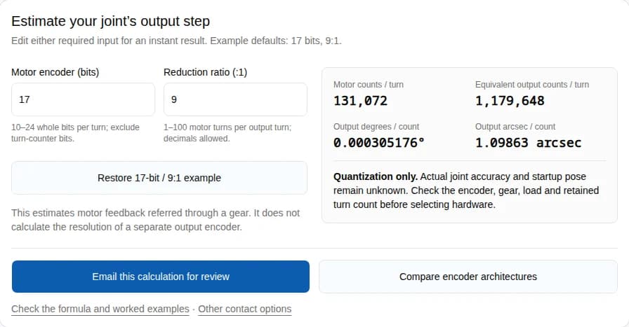
Estimate your joint’s output step

Edit either required input for an instant result. Example defaults: 17 bits, 9:1.

10–24 whole bits per turn; exclude turn-counter bits.

1–100 motor turns per output turn; decimals allowed.

This estimates motor feedback referred through a gear. It does not calculate the resolution of a separate output encoder.

Motor counts / turn
131,072
Equivalent output counts / turn
1,179,648
Output degrees / count
0.000305176°
Output arcsec / count
1.09863 arcsec

Quantization only. Actual joint accuracy and startup pose remain unknown. Check the encoder, gear, load and retained turn count before selecting hardware.

Check the formula and worked examples · Other contact options

Published by QDD Motors · Published · Reviewed

Four decisions before selecting an encoder

1. Specify joint accuracy separately

A smaller calculated step is not an accuracy specification. Ask for loaded output error and repeatability.

Evidence & limits

2. Resolve startup position

Motor single-turn data can represent several joint poses after reduction. Verify the turn state before enabling motion.

Evidence & limits

3. Measure after the error source

Consider an output sensor when joint position must be observed independently of the gear.

Evidence & limits

4. Validate the assembled joint

Dual feedback requires calibration and tuning. It does not guarantee a fixed arcminute accuracy.

Evidence & limits

Method: bits → motor counts → output step

Let b be the motor encoder’s bits within one turn, and N the exact motor turns per output turn. For ideal rigid gearing:

Motor counts = 2^b

Equivalent output counts = 2^b × N

Output step (°) = 360 / (2^b × N)

Arcminutes = degrees × 60; arcseconds = degrees × 3,600

Equivalent counts express an angular increment, not unique absolute output positions. A non-integer ratio may yield fractional equivalent counts. The tool assumes ideal transmission and excludes encoder error, backlash, compliance, temperature, sampling and controller behavior. Displayed angles use six significant figures.

Calculated examples — ideal kinematics, not measured performance
Motor bits / ratioEquivalent counts / output turnOutput step (degrees)Output step (arcsec)
14 bits / 6:198,3040.00366211°13.1836
17 bits / 9:1 (default)1,179,6480.000305176°1.09863
17 bits / 1:1 (direct drive)131,0720.00274658°9.88770
24 bits / 100:1 (tool limit)1,677,721,6002.14577e-7°0.000772476
Absolute encoder QDD motor calculator with 17 bits and 9:1 reduction producing 1.09863 arcseconds per output count
Reproduced in this calculator on September 26, 2026: 17 motor bits, 9:1 reduction, 1,179,648 equivalent output counts and 1.09863 arcsec per count. Screenshot of software execution, not a motor measurement, accuracy test or customer result.

Motor-only vs dual encoder feedback

One motor sensor: gear error is downstream of the measurementMotor + encoder MReduction gear N:1Joint (not measured)MGear backlash remains unobserved
Motor-only feedback estimates the joint through the ratio. It cannot directly measure downstream motion.
Two sensors: motor feedback and direct joint position feedbackMotor + encoder MReduction gear N:1Joint + encoder JMJJ: position · M: velocity / commutation
Dual feedback observes the joint. The controller and mechanics still set achievable performance.
Architecture tradeoffs — achieved error requires testing
DecisionMotor encoder onlyMotor + output encoder
Measured positionMotor shaft; joint angle inferred through NMotor shaft and joint angle measured separately
Gear error visibilityDownstream backlash/deflection not directly measuredJoint sensor exposes downstream position error; mechanics remain
Positioning accuracyUnknown without a gear and sensor error budgetUnknown without sensor calibration and loaded closed-loop tests
Startup referenceNeeds valid turn state or an unambiguous travel/reference constraintJoint reading may establish pose within its measurement range; check offsets and turn coverage
Integration costFewer sensors; budget for reference strategy and mechanical errorExtra sensor, mounting, interface, calibration and dual-loop tuning
Selection triggerConsider if verified joint error meets the application budgetConsider if direct joint observability is required

Controller example: Evidence & limits. Compatibility with a particular drive or motor module must be confirmed. This comparison makes no universal accuracy or price claim.

Need to choose a feedback architecture? Request a joint feedback review with your travel, accuracy target and power-off motion conditions.

Startup check: the 9:1 ambiguity

For an ideal 9:1 gear, one motor turn moves the joint 40°. With no turn history and a full output revolution allowed, the same motor single-turn reading corresponds to nine possible joint positions, spaced 40° apart. Higher bit depth does not identify which turn occurred.

This is derived from N = 9 and a single-turn sensor, not a measured fault rate. Restricted joint travel plus a validated reference can remove the ambiguity; the gear ratio alone cannot.

Power-cycle acceptance checks
ConfigurationQuestion before motionMinimum next step
Single-turn motor encoderCan two allowed joint poses share this motor reading?Prove unique mapping over travel or establish a reference
Multi-turn motor encoderAre turns retained and unpowered movements captured?Test the documented retention method and power-loss cases
Output absolute encoderDoes its range cover joint travel and is zero calibrated?Verify mounting, offset, wraparound and startup validity

Evidence & limits. An absolute reading alone is not a robot safety function or proof that motion can start.

Three worked selection scenarios

Illustrative engineering scenarios, not customer results or product promises.

A. A 14-bit, 6:1 joint with a 0.1° target

The tool gives 0.00366211° per count, about 27 steps across the target. Quantization fits that target, but total accuracy is still unproven. Request loaded reversal error and encoder accuracy before accepting the joint.

B. A 17-bit, 9:1 joint that moves while unpowered

The default step is 1.09863 arcsec. That fine increment does not resolve the nine possible startup poses over a full joint turn. Specify validated persistent turn tracking, output feedback, or a reference procedure.

C. A 17-bit motor sensor plus a 14-bit output sensor

At 9:1 the motor-referred step is 1.09863 arcsec; the independent output sensor step is 360/16,384 = 0.0219727°, or 79.1016 arcsec. The output sensor adds observability, even though its step is coarser. Choose it against the joint error budget and controller requirements.

Risks, cost and alternatives

Engineering review checklist — recommendations to verify on your assembly
RiskConsequenceMitigation / alternative
Buying by bit depth aloneA fine number masks larger mechanical errorAllocate a joint error budget; request accuracy and repeatability tests
Unverified restart stateJoint pose may be wrong after a power cycleTest retained turns or output reference before enabling motion
Dual-loop complexityMore commissioning time; poor tuning can cause oscillationVerify drive support and test reversals with the intended load
Increasing ratio just for resolutionChanges motion, friction and reflected inertia tradeoffsSelect torque/speed and backdrive requirements first; compare 1:1 if feasible
Sensor integration costAdded mounting, wiring, calibration and service effortRequest a complete integration quote and replacement procedure

Low-ratio gearing is a QDD design approach, not proof of back-drivability: Evidence & limits. Tuning limitations: Evidence & limits. These are review actions, not certified operating procedures.

Evidence, scope and unknowns

Sources reviewed . Manufacturer references describe principles and their own systems; they do not establish specifications for an unnamed QDD Motors product.

Renishaw: Optical encoders FAQ

Separates measurement step, agreement with true position, and repeatability. These are different specifications.

Limit: Definitions apply to the calculation; this is not a QDD module accuracy test.

Same Sky: Why multi-turn encoders matter

Single-turn readings repeat each revolution. Turn counting and its behavior across power loss depend on the encoder design.

Limit: Confirm retention and unpowered-motion behavior for the exact encoder. The 9:1 ambiguity example below is our kinematic derivation.

Synapticon: Dual loop cascaded position control

Documents motor-side commutation/velocity feedback and output-side position feedback, with the gear ratio explicitly configured.

Limit: This architecture reference does not specify a universal achieved positioning error.

Synapticon: Position control loop tuning

Requires mounted and calibrated sensors and a correct gear ratio; strong nonlinearities limit a linear tuning model.

Limit: Validate reversal, settling and loaded motion on your assembly; feedback does not remove physical clearance.

Yu et al. (2020): QDD hip exoskeleton research

Studies a high-torque-density motor with a low-ratio transmission, including measured backdrive behavior.

Limit: Research on one actuator supports the design approach, not a fixed QDD ratio range or performance guarantee for other joints.

What this page establishes
Known from the toolNot establishedEvidence to request
Ideal output quantization for your inputsActual positioning error and repeatabilityLoaded joint test report with conditions
Motor turns per output turnStartup pose and power-off trackingEncoder datasheet and restart test
Single vs dual feedback rolesInterface compatibility, price and availabilityModel-specific drawing, drive support and quote

Selection FAQ

Does an absolute encoder eliminate homing?

Only when the measured state uniquely identifies the required joint position, with valid calibration and any necessary turn information. Check the startup table above.

Can I enter the total multi-turn bit count?

No. Enter bits within one motor revolution. Turn-counter bits increase the position range, not the angular resolution within a turn.

Does a dual encoder remove backlash?

It can let the control loop observe and correct joint position error. Physical clearance remains; response under reversal and load must be tested.

Does a low ratio guarantee back-drivability?

No. Gear construction, friction, seals, bearings and motor behavior also matter. Ask for measured backdrive torque under stated conditions.

Can I calculate output-encoder resolution here?

For an encoder mounted directly on the joint, use its per-turn bits with ratio 1. Do not multiply those bits by the upstream gear ratio.

Which encoder interface should I request?

Specify the exact sensor protocol and the drive’s supported inputs, timing and fault handling. A motor module’s network interface alone does not prove encoder compatibility.

What if I do not know the gear ratio?

Use the exact reduction from the assembly datasheet. Ask engineering to identify it before treating the calculated value as an input to selection.

When is direct drive worth comparing?

Compare a gearless design when transmission error or backdrive behavior dominates. Verify torque, size, thermal capacity and controller requirements for the same duty cycle.

Review your absolute encoder QDD motor requirements

Send required joint accuracy, travel, torque/speed, power-off motion, encoder location, controller interface and quantity. Ask for model-specific feedback options, an output error report and a startup procedure.

Inquiry Email

[email protected]

Include target torque/speed, quantity, and delivery location.

Instant Chat

+86 188 5797 1991

Opens a direct WhatsApp thread with the RFQ message prefilled.